Method and apparatus for adaptive carrier allocation and power control in multi-carrier communication systems

a communication system and carrier technology, applied in the field of carrier allocation technique for use in multi-carrier communication systems, can solve problems such as in-band distortion

Inactive Publication Date: 2004-06-15
KAON SYST +1
View PDF41 Cites 336 Cited by
  • Summary
  • Abstract
  • Description
  • Claims
  • Application Information

AI Technical Summary

Problems solved by technology

Note that operating the PA of a subscriber closer to...

Method used


Image

  • Method and apparatus for adaptive carrier allocation and power control in multi-carrier communication systems
  • Method and apparatus for adaptive carrier allocation and power control in multi-carrier communication systems
  • Method and apparatus for adaptive carrier allocation and power control in multi-carrier communication systems

Examples


Embodiment Construction

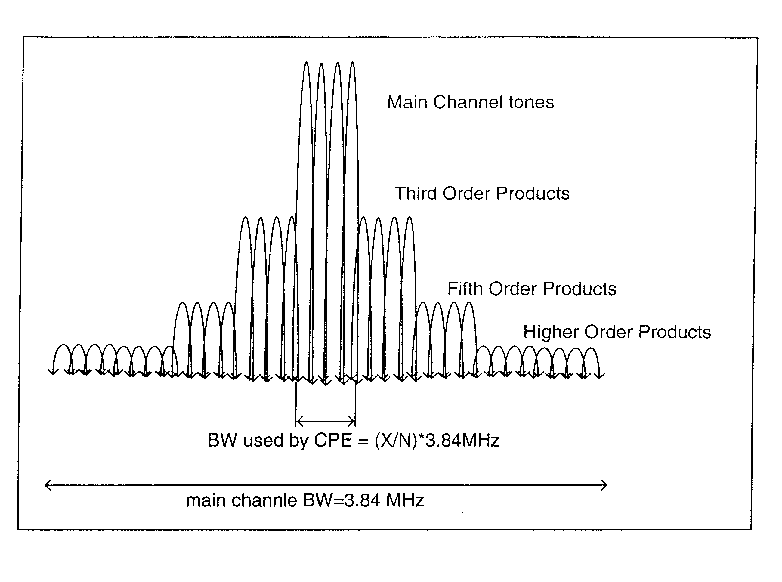
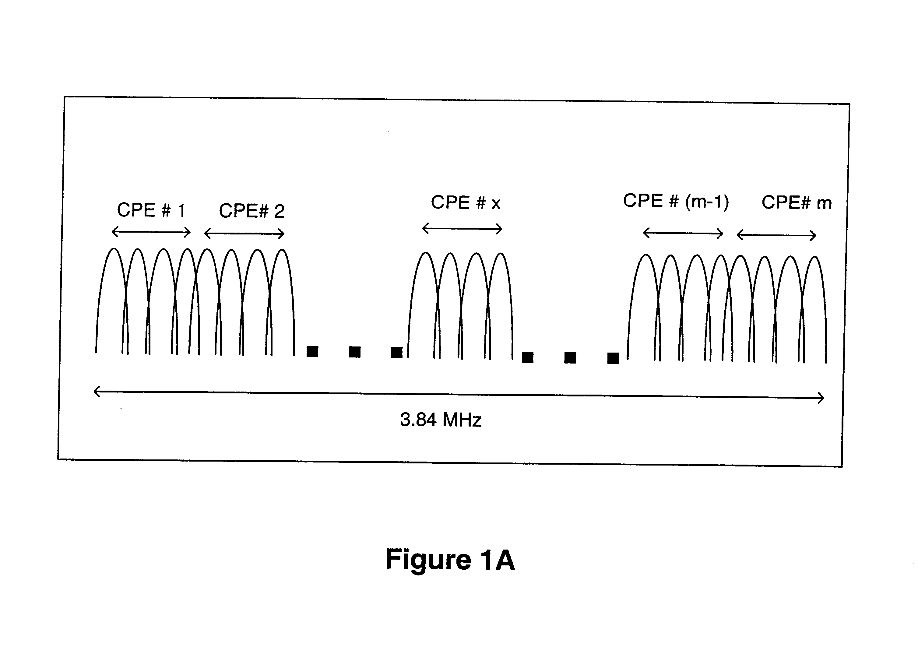
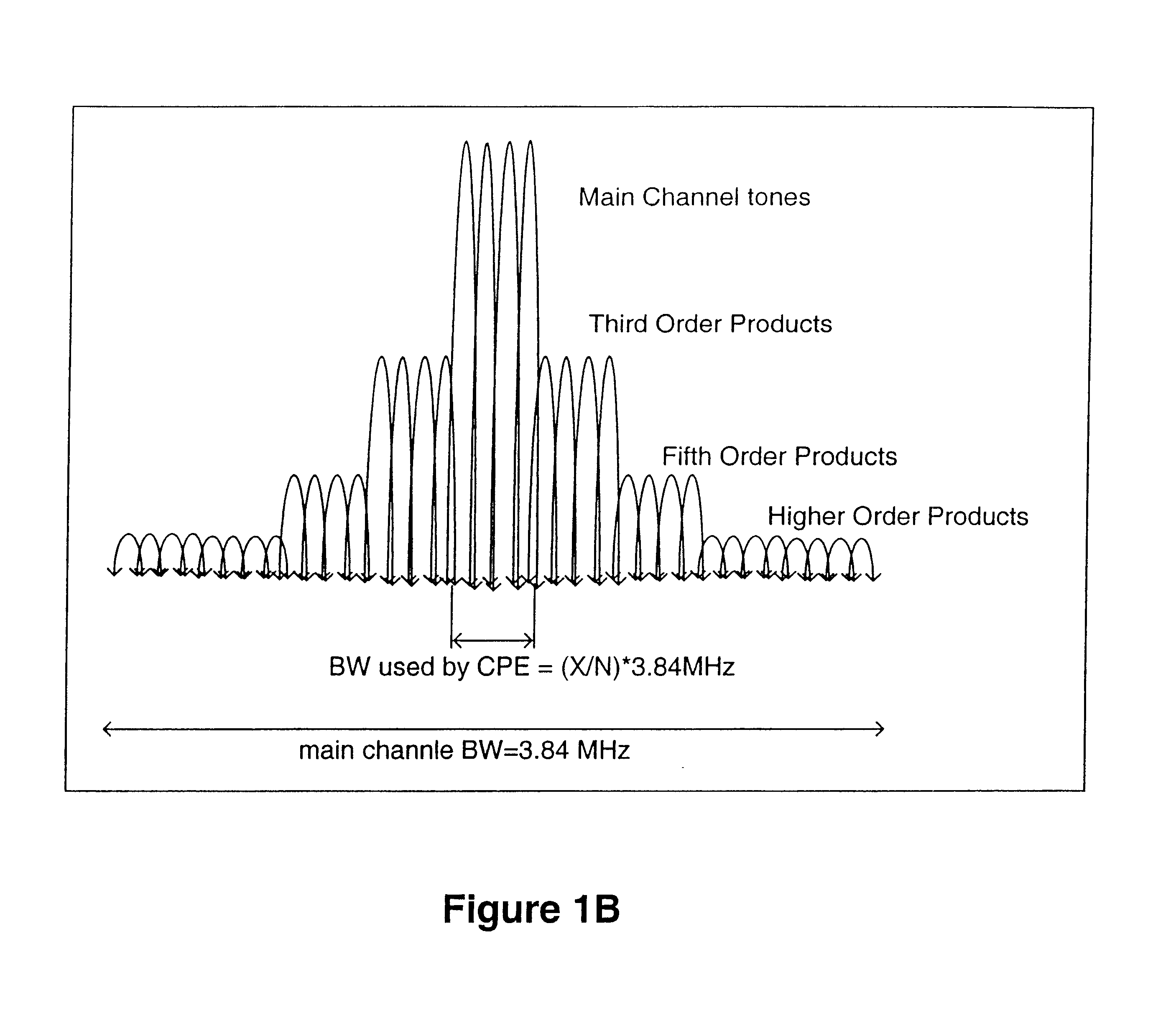
A carrier allocation technique for use in multi-carrier systems is described. The carrier allocation technique selects carriers, or subcarriers, of a band to allocate to a subscriber or Customer Equipment (CE) for their use. In one embodiment, the allocation is performed such that carriers closer to or at the center of the band are allocated to subscriber units and CEs further away from a base station and carriers closer to the edge of the band are allocated to those CEs and subscriber units closer to the base station.

In one embodiment, the technique described herein increases the transmitter radio frequency (RF) power available from a power amplifier (PA) of the CPE, CE, terminal, subscriber unit, portable device, or mobile by exploiting the multi-carrier nature of multiple carrier systems, such as, for example, an orthogonal frequency-division multiple access (OFDM) system. This technique may double or even quadruple the PA output power, resulting in balancing RF link design in a ...


PUM


Abstract

An apparatus and process for allocating carriers in a multi-carrier system is described. In one embodiment, the process comprises determining a location of a subscriber with respect to a base station, selecting carriers from a band of carriers to allocate to the subscriber according to the location of the subscriber with respect to the base station, and allocating selected carriers to the subscriber.

Description

The present invention relates to the field of multi-carrier communication systems; more particularly, the present invention relates to allocating carriers and performing power control in a multi-carrier system.With high-speed wireless services increasingly in demand, there is a need for more throughput per bandwidth to accommodate more subscribers with higher data rates while retaining a guaranteed quality of service (QoS). In point-to-point communications, the achievable data rate between a transmitter and a receiver is constrained by the available bandwidth, propagation channel conditions, as well as the noise-plus-interference levels at the receiver. For wireless networks where a base-station communicates with multiple subscribers, the network capacity also depends on the way the spectral resource is partitioned and the channel conditions and noise-plus-interference levels of all subscribers. In current state-of-the-art, multiple-access protocols, e.g., time-division multiple acc...

Claims


Application Information

Patent Timeline
IPC IPC(8): H04B7/005H04L5/02
CPCH04W52/367H04L5/023H04W52/24H04W52/50
Inventor MEIYAPPAN, PALANIAPPAN
Owner KAON SYST
Why Eureka
Try Eureka