
Vapor compression system and method

a technology of vapor compression system and vapor compression chamber, which is applied in the direction of mechanical equipment, refrigeration components, lighting and heating apparatus, etc., can solve the problems of reducing the shelf life of food products contained in refrigeration/freezer cabinets, increasing the load on the case, and reducing the heat transfer efficiency, so as to reduce the velocity and hence the defrosting efficiency, the effect of less cooling tim

Inactive Publication Date: 2004-06-22
XDX GLOBAL LLC
View PDF188 Cites 19 Cited by
  • Summary
  • Abstract
  • Description
  • Claims
  • Application Information

AI Technical Summary

Benefits of technology

It is, therefore, an object of the present invention as to provide a vapor compression refrigeration method and apparatus having improved heat transfer efficiency along substantially the entire length of the cooling coils in the evaporator.
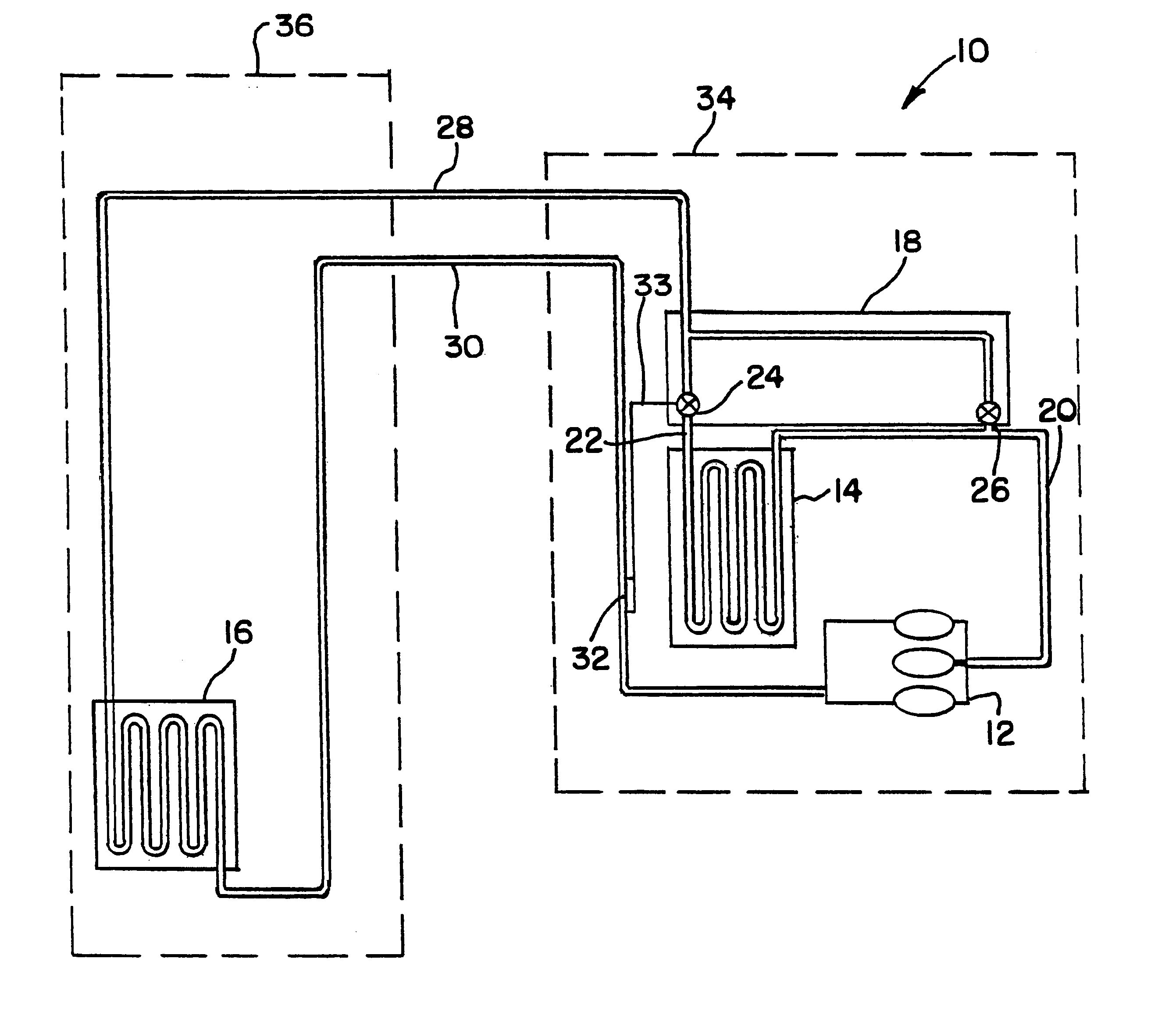
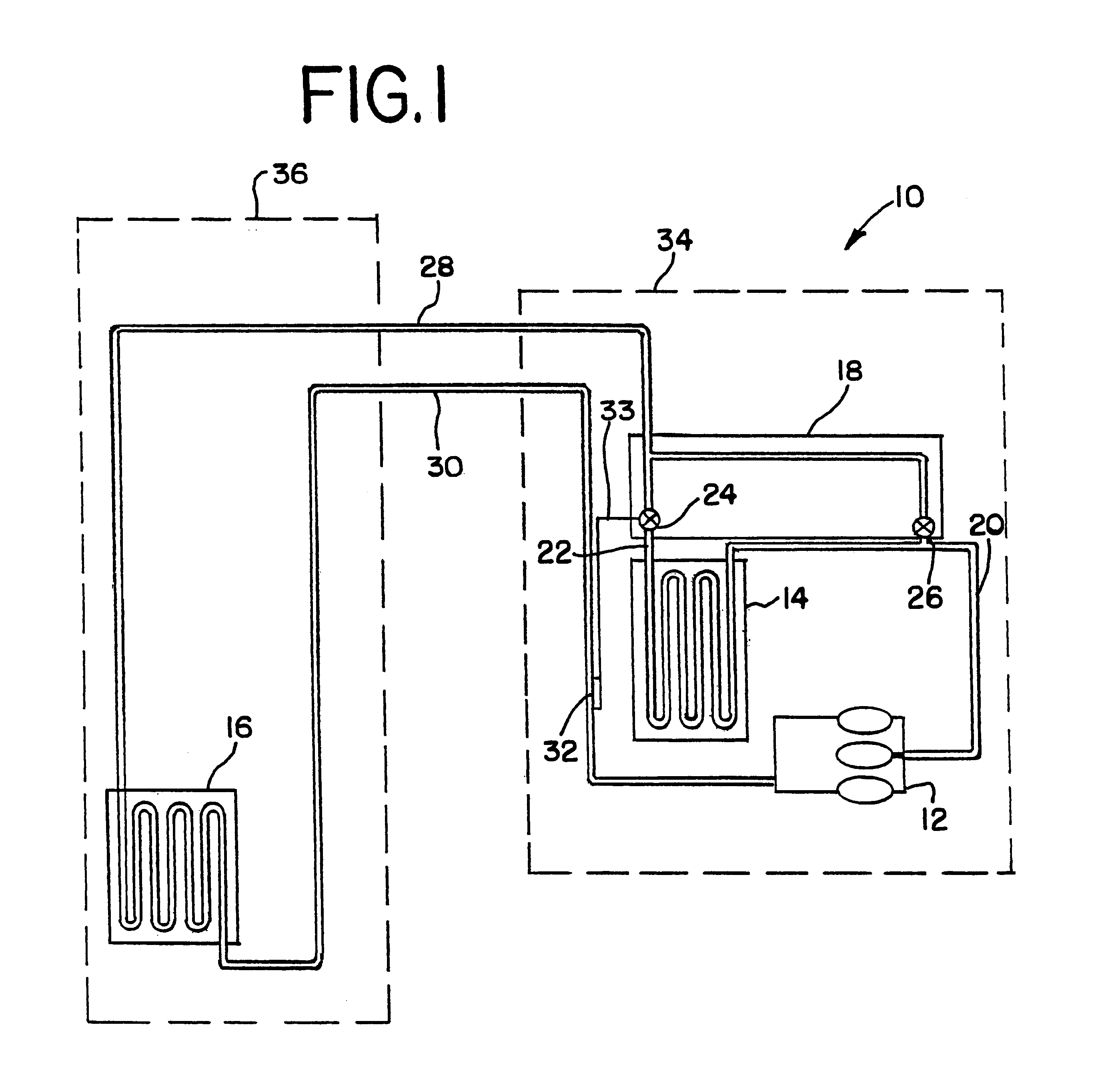
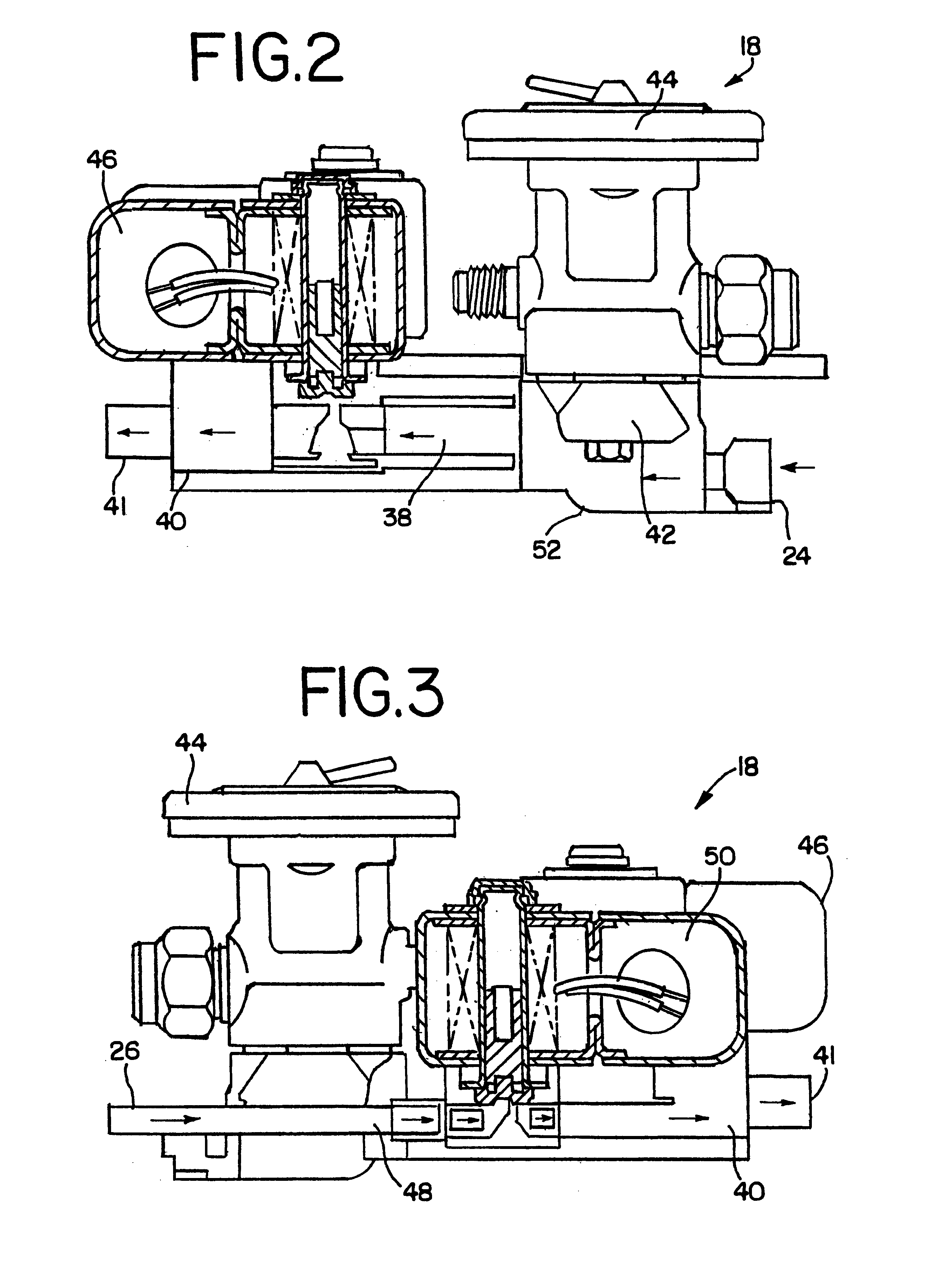
The forward flow defrost capability of the invention also offers numerous operating benefits as a result of improved defrosting efficiency. For example, by forcing trapped oil back into the compressor, liquid slugging is avoided, which has the effect of increasing the useful life of the equipment. Furthermore, reduced operating costs are realized because less time is required to defrost the system. Since a flow of hot gas can be quickly terminated, the system can be rapidly returned to normal cooling operations. When frost is removed from evaporator 16, temperature sensor 32 detects a temperature increase and the heat transfer fluid in suction line 30. When the temperature rises to a given set point, gating valve 50 in multifunctional valve 18 is closed and the system is ready to resume refrigeration operation.

Problems solved by technology

This refrigerant feed and the low flow rates inherently associated therewith produce relatively inefficient cooling particularly along the initial portions of the cooling coil(s) resulting in the build-up of frost or ice at such locations which further reduces the heat transfer efficiency thereof.
In commercial systems, such as open refrigerated display cabinets, the build-up of frost can reduce the rate of air flow to such an extent that an air curtain is weakened resulting in an increased load on the case.
Moreover, this build-up of frost or ice on the evaporator cooling coils necessitates frequent defrosting, thereby reducing the shelf-life of food products contained in the refrigeration / freezer cabinets and increasing the power consumption and cost of operation.

Method used


Image

  • Vapor compression system and method
  • Vapor compression system and method
  • Vapor compression system and method

Examples


example ii

In the Tyler Chest Freezer equipped with electric defrosting circuits, the low temperature operating test was carried out using the electric defrosting circuit to defrost the evaporator. The time needed for the XDX system and an electric defrost system to complete defrost and to return to the 5.degree. F. (-14.4.degree. C.) operating set point appears in Table C below.

As shown above, the XDX system using forward-flow defrost through the multifunctional valve needs less time to completely defrost the evaporator, and substantially less time to return to refrigeration temperature.

example iii

This Example compares the performance of a vapor compression refrigeration system of the present invention (the XDX system) with that of a conventional system operating in the medium temperature range.

The refrigeration circuit of an 8 ft. (2.43 m) IFI meat case (Model EM5G-8) was equipped with a multifunctional device as described herein (which included a Sporlan Q-body thermostatic expansion valve). A like thermostatic expansion valve was plumbed into a bypass line so that the refrigeration circuit could be operated either as an XDX refrigeration system or as conventional refrigeration system.

This refrigeration circuit included an evaporator feed line (in the XDX mode) having an outside tube diameter of 0.5 in. (1.27 cm) and a run length (compressor to evaporator) of approximately 35 ft. (10.67 m). The liquid feed line (in the conventional mode) had an outside tube diameter of 0.375 in. (0.95 cm) and approximately the same run length. Both modes of operation used the same condenser...

example iv

This Example compares the performance of a vapor compression refrigeration system of the present invention (the XDX system), an annular flow refrigeration system, with that of a conventional system operating in the low temperature range.

The refrigeration circuit of a four door IFI freezer (Model EPG-4) was equipped with a multifunctional device as described herein (which included a Sporlan Q-body thermostatic expansion valve). A like thermostatic expansion valve was plumbed into a bypass line so that the refrigeration circuit could be operated either as an XDX refrigeration system or a conventional refrigeration system.

This refrigeration circuit included an evaporator feed line (in the XDX mode) having an outside tube diameter of 0.5 in. (1.27 cm) and a run length from the compressorized unit (the assembly of the compressor, condenser and receiver) to the evaporator of approximately 20 ft. (6.10 m) was the same for both the XD and conventional modes. The liquid feed line (in the con...


PUM


Abstract

A vapor compression refrigeration and freezer system includes a compressor, a condenser, an expansion devise and an evaporator which includes an evaporator coil having an inlet and an outlet which coil is in heat exchange relation with an air medium along substantially the entire coil length. The inlet to the evaporator coil is in flow communication with an outlet of the expansion devise via an evaporator feedline. The expansion device can include a multifunctional valve that cooperates with the evaporator feedline to supply the evaporator coil inlet with a mixture of refrigerant vapor and liquid at a linear velocity and with relative amounts of vapor and liquid which are sufficient to provide efficient heat transfer along substantially the entire length of the coil, substantially reducing the build-up of frost on the evaporator coil and enabling the system to be operated without requiring a defrosting cycle over a substantially increased number of operating cycles compared to conventional refrigeration and freezer systems operating at the same cooling load and evaporating temperature conditions.

Description

The present invention generally relates to vapor compression systems and, more particularly, to vapor compression refrigeration, freezer and air conditioning systems. In this regard, an important aspect of the present invention concerns improvements in the efficiency of vapor compression refrigeration systems which are advantageously suited for use in commercial medium and low temperature refrigeration / freezer applications.Vapor compression refrigeration systems typically employ a fluid refrigerant medium that is directed through various phases or states to attain successive heat exchange functions. These systems generally employ a compressor which receives refrigerant in a vapor state (typically in the form of a super heated vapor) and compresses that vapor to a higher pressure which is then supplied to a condenser wherein a cooling medium comes into indirect contact with the incoming high pressure vapor, removing latent heat from the refrigerant and issuing liquid refrigerant at o...

Claims


Application Information

Patent Timeline
Patent Type & Authority Patents(United States)
IPC IPC(8): F25B41/04F25B1/00F25B41/06F25B47/02
CPCF25B41/04F25B2500/01F25B41/20
Inventor WIGHTMAN, DAVID A.
Owner XDX GLOBAL LLC
Learn More