Valve actuator having small isolated plunger

a valve actuator and plunger technology, applied in the direction of valve operating means/releasing devices, functional valve types, mechanical devices, etc., can solve the problems of reducing and affecting the longevity of the actuator

Inactive Publication Date: 2004-06-22
ARICHELL TECH INC
View PDF70 Cites 39 Cited by
  • Summary
  • Abstract
  • Description
  • Claims
  • Application Information

AI Technical Summary

Problems solved by technology

This makes constraints on power dissipation severe in many instances.
But we have recognized that this very smallness can detract from actuator longevity when the actuator employs an incompressible-fluid-filled plunger chamber.
It turns out that a significant factor detracting from the longevity of small actuators employing incompressible-fluid-filled plunger chambers is the loss of the incompressible fluid as a result of diffusion.

Method used


Image

  • Valve actuator having small isolated plunger
  • Valve actuator having small isolated plunger
  • Valve actuator having small isolated plunger

Examples


Embodiment Construction

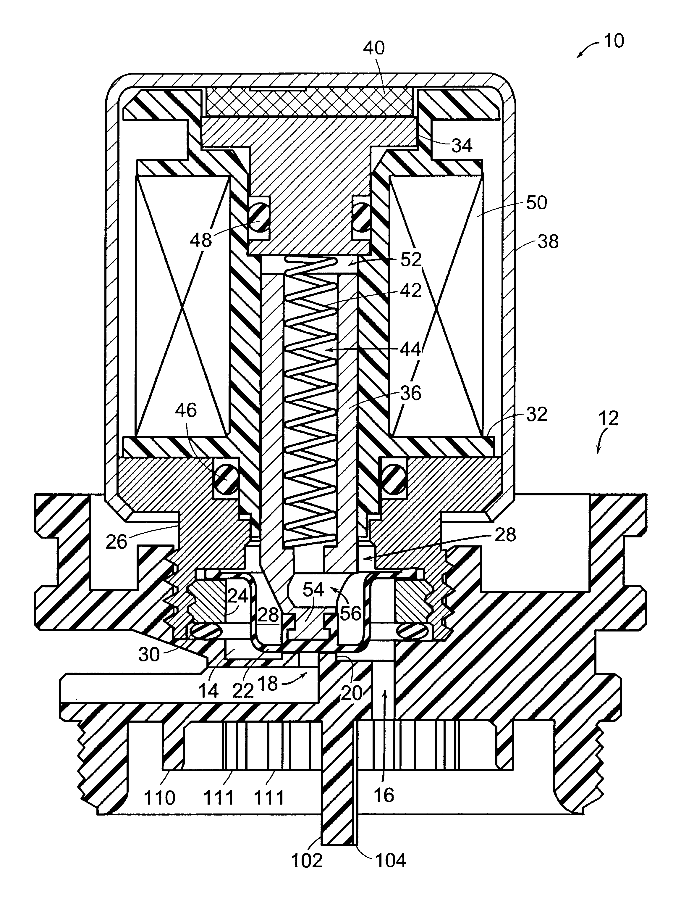
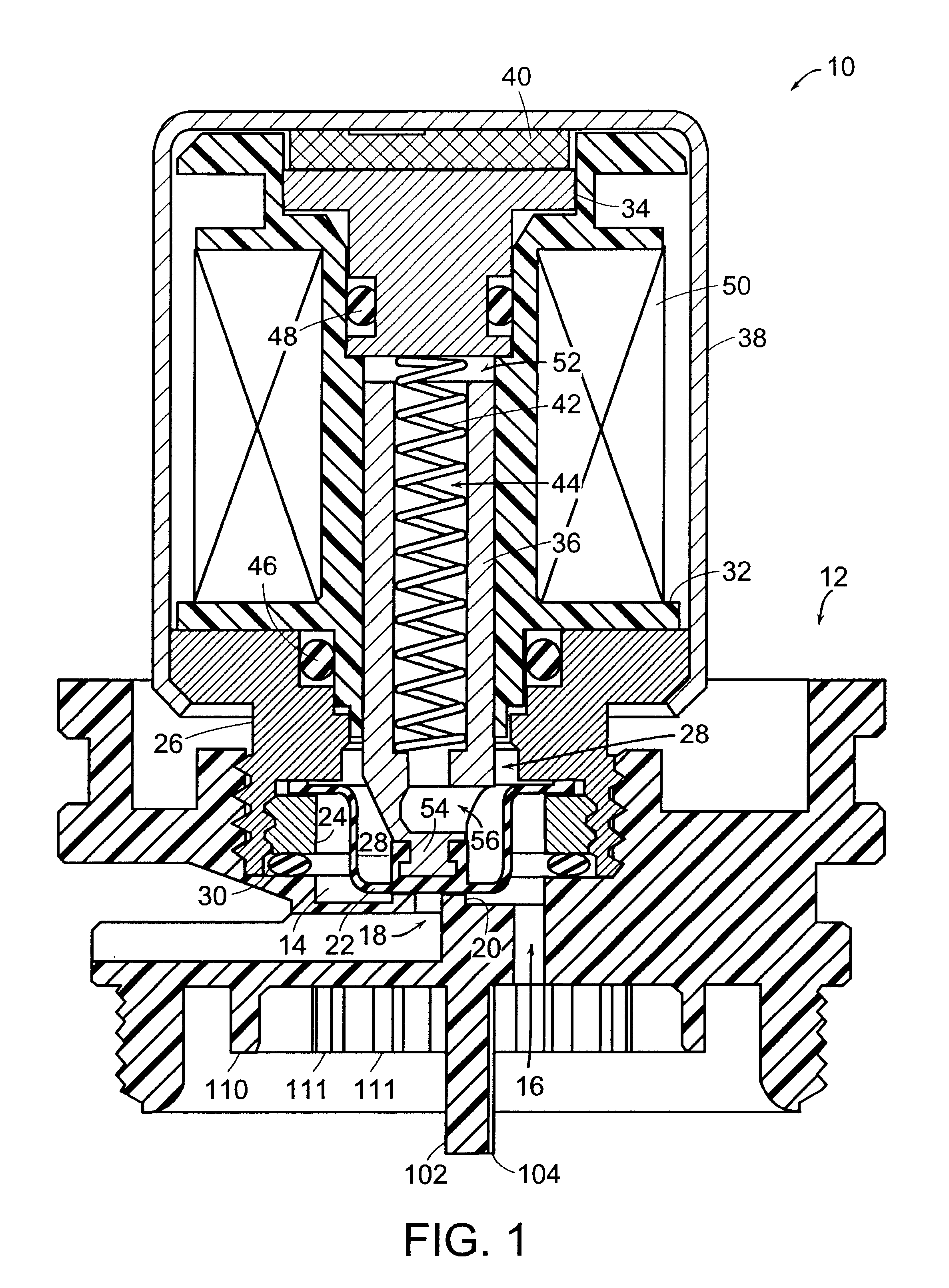
. 1 depicts an actuator 10 threadedly secured to a pilot-valve body 12. Together with the actuator 10, the pilot-valve body 12 forms a pilot-valve chamber 14. The pilot-valve body member 12 forms an inlet passage 16 by which fluid enters the pilot-valve chamber, and it also forms a pilot-valve outlet passage 18 by which fluid can leave the chamber when the pilot valve is open.

The pilot-valve body also forms an annular valve seat 20 past which fluid must flow to leave the pilot-valve chamber 14 through the outlet 18. In the state that FIG. 1 illustrates, though, the actuator 10's flexible diaphragm 22 is seated on the valve seat 20 and thereby prevents such flow: the pilot valve is closed. A washer 24 threadedly secured to the actuator 10's front pole piece 26 traps the diaphragm 22's outer end against that pole piece. The diaphragm thereby isolates a chamber 28 from the fluid in the pilot-valve chamber. An O-ring 30 similarly prevents the fluid in the pilot-valve chamber 14 from esc...


PUM


Abstract

A solenoid plunger (36) is disposed for reciprocation in a plunger pocket that is formed by the stationary parts of a solenoid-type actuator (10). A flexible diaphragm (22) closes the plunger pocket's open mouth and is deformed by movement of a plunger (36) between an open position, in which it is displaced from a valve seat (20), and a closed position, in which it is seated on the valve seat and thereby prevents flow from a valve inlet (16) to a valve outlet (18). The diaphragm thereby isolates the plunger from the fluid thereby being controlled, but a separate, incompressible fluid fills the chamber in which the plunger reciprocates. A through-plunger passage (44, 56) provides a low-flow-resistance path for the incompressible fluid to flow into and out of the portion (52) of the plunger chamber behind the plunger as the plunger moves. This reduces actuation time and thus the energy required for an actuation. The chamber in which the plunger reciprocates is formed by elements (22, 26, 32, and 34) through which the incompressible fluid can diffuse only very slowly, so the actuator can be long-lived even if it small in size.

Description

1. Field of the InventionThe present invention concerns solenoid-type actuators and in particular actuators of the type whose armatures are disposed in fixed-volume sealed chambers.2. Background InformationElectromagnetically operated valves ordinarily employ solenoid-type actuators. An armature, often referred to as a "plunger" in valve-type applications, is so disposed in a guide as to allow it to reciprocate. The plunger includes ferromagnetic material that forms part of the path taken by magnetic flux that results when current flows in a solenoid coil. The magnetic path's reluctance varies with plunger position. In accordance with well-known magnetic principles, therefore, the flow of solenoid current results in a magnetic force that tends to urge the plunger in one or the other direction.In an increasingly large number of valve installations, the power employed to drive the solenoid coil comes from batteries. This makes constraints on power dissipation severe in many instances....

Claims


Application Information

Patent Timeline
Patent Type & Authority Patents(United States)
IPC IPC(8): E03D1/36E03D5/00E03D1/30E03D5/10
CPCE03D1/36E03D5/10
Inventor HERBERT, KAYGULER, FATIHPARSONS, NATAN E.
Owner ARICHELL TECH INC
Why Eureka
Try Eureka