Multidimensional array and fabrication thereof

a technology of multi-dimensional arrays and fabrication methods, applied in the field of multi-dimensional arrays, can solve the problems of difficult construction of transducer arrays with the required elevation properties, increased cost and complexity, and generally lower beam resolution

Inactive Publication Date: 2004-07-06
PARALLEL DESIGN
View PDF9 Cites 21 Cited by
  • Summary
  • Abstract
  • Description
  • Claims
  • Application Information

AI Technical Summary

Problems solved by technology
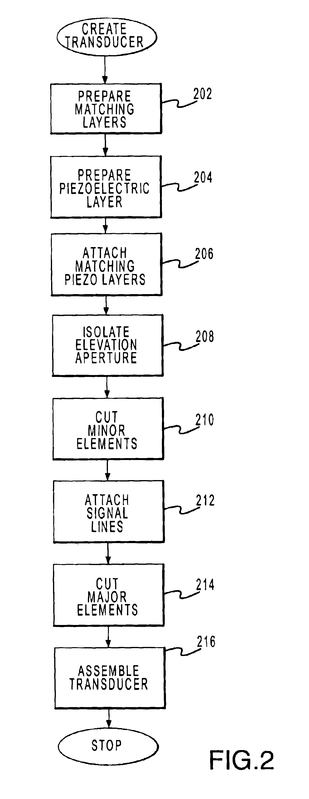
Objects that are not in the azimuth imaging plane of the beam generally exhibit lower resolutions because the 1D array cannot typically steer the beam in planes other than the azimuth.
Additional channels typically result in additional expense and complexity, so it is of interest to evaluate how much performance can be improved with a moderate increment in channel count.
Second, building transducer arrays with the required elevation properties has been difficult since the already small elements must be further subdivided and independently controlled.
The creation of 1.5-D and 2-D arrays typically poses several problems.
Adequately isolating aperture strips electrically and acoustically is one problem.
This method, however, typically produces unwanted intra-element cross talk (e.g. electrical or acoustic interference between adjoining transducer elements).
A second problem common in multi-dimensional transducer arrays involves providing a reliable method of interconnecting the aperture strips.
This method typically produces unwanted reflections from the flexible printed circuit and interferes with the pulse-echo response.
Additionally, current methods for adequately isolating and interconnecting aperture strips are complicated and costly.
U.S. Pat. No. 5,704,105 issued Jan. 6, 1998 to Venkataramani, et al. and incorporated herein by reference, for example, discloses another technique for creating 1.5-D and 2-D transducer arrays, but the technique described therein is complicated to implement and may not adequately isolate the various elements.

Method used


Image

  • Multidimensional array and fabrication thereof
  • Multidimensional array and fabrication thereof
  • Multidimensional array and fabrication thereof

Examples


Embodiment Construction

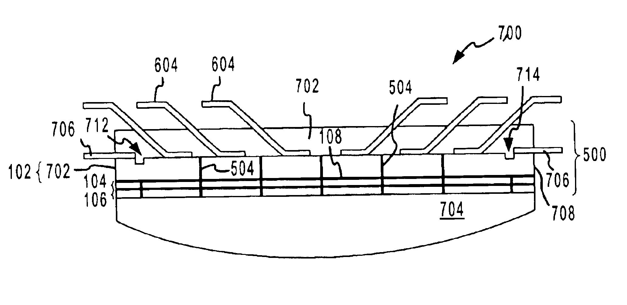
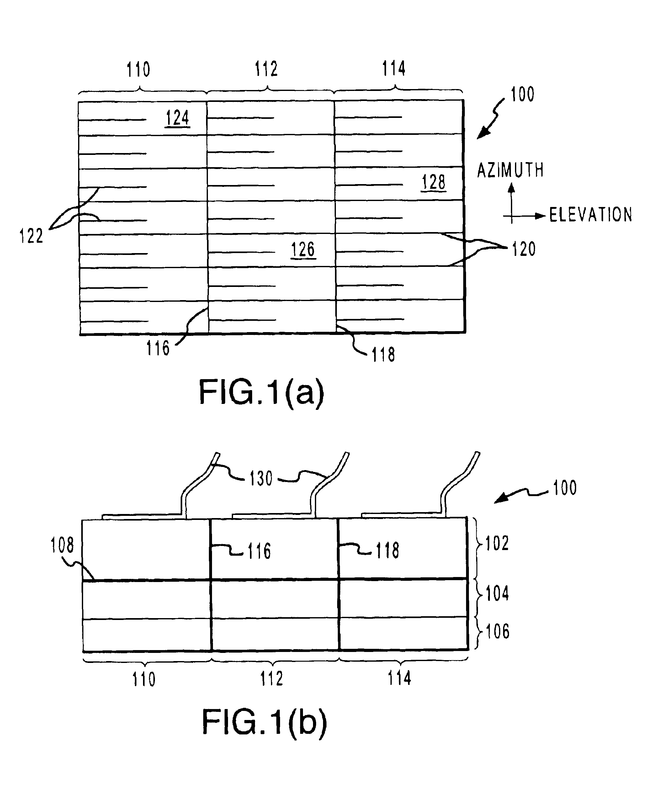
The exemplary embodiment of the invention disclosed herein primarily discusses the construction of a multi-dimensional array for use in a medical imaging transducer. However, any number of other embodiments fall within the ambit of the present invention. For example, the devices and techniques described herein could be used in conjunction with other types of transducer systems, such as audio loudspeakers, nondestructive evaluation, non-invasive surgeries, dentistry, and the like. Similarly, the techniques described herein in conjunction with 1.5-D arrays could also be used to implement a 2-D array, or any other multi-dimensional structure. Further, it will be appreciated that the alignment, spatial orientation, and relative positions of the various elements recited herein could be modified in any way without departing from the scope of the invention. For example, although the terms "azimuth" and "elevation" are used herein to simplify discussion, it would be possible to formulate tr...


PUM

PropertyMeasurementUnit
frequencyaaaaaaaaaa
thicknessaaaaaaaaaa
speedaaaaaaaaaa

Abstract

According to various aspects of the invention, a transducer is manufactured by providing a substrate assembly, making major element cuts in the substrate assembly in a first direction, making minor element cuts in the substrate assembly in a second direction, positioning a plurality of signal lines (such as a flex circuit) on the substrate assembly such that the plurality of signal lines is aligned with said minor element cuts, and making major element cuts in the substrate assembly in the second direction after said plurality of signal lines is positioned.Various aspects of the invention also include a multi-dimensional transducer having a plurality of elements, wherein the transducer includes a conductor; a piezoelectric assembly assembled with said conductor and having a first plurality of cuts in a first direction; anda matching layer assembly having a second plurality of aperture cuts in the first direction, wherein the matching layer is coupled to the conductor opposite the piezoelectric assembly such that the first and second pluralities of elevation cuts are aligned to isolate the plurality of elements in an elevation dimension.

Description

This invention relates generally to transducers. More particularly, the invention relates to a 1.5 dimensional ultrasonic transducer array suitable for use in medical imaging, as well as to methods of transducer use and construction.Transducers are devices that convert electrical energy to mechanical energy, or vice versa. A common application of transducers is in ultrasonic imaging, which is often used in medical applications, non-destructive testing, and the like.Transducers used for medical imaging typically include one or more transducer elements that may be matched to and driven by electronics connected to the transducer via a coaxial cable or the like. In an ultrasonic imaging application, for example, a typical transducer suitably converts an electrical signal generated by the electronics into mechanical vibrations (e.g. ultrasonic sound waves) that may be transmitted and reflected through the human body. The vibrations may be produced by one or more piezoelectric elements th...

Claims


Application Information

Patent Timeline
Patent Type & Authority Patents(United States)
IPC IPC(8): B06B1/06A61B8/00H02N2/00H04R17/00H04R31/00
CPCB06B1/0607B06B1/067B06B1/0622Y10T29/49005
Inventor HATANGADI, RAMCHANDRAN, SANJAYCHARTRAND, DAVE
Owner PARALLEL DESIGN
Why Eureka
Try Eureka