Processing device

a processing device and processing technology, applied in the direction of metal working apparatus, connection formation by deformation, manufacturing tools, etc., can solve the problems of significant operating interruption of the device and unsatisfactory results

Inactive Publication Date: 2004-07-20
CARL FREUDENBERG KG
View PDF11 Cites 15 Cited by
  • Summary
  • Abstract
  • Description
  • Claims
  • Application Information

AI Technical Summary

Problems solved by technology

In this context, the result is significant operating interruptions...

Method used


Image

  • Processing device
  • Processing device
  • Processing device

Examples


Embodiment Construction

The invention is based on the objective of refining a device of this type such that the result is significantly reduced refitting times for the adaptation to cable ends being processed using contact elements that are different from each other

This objective is achieved according to the present invention in a device of the type cited above having the characterizing features of claim 1. The subclaims make reference to advantageous embodiments.

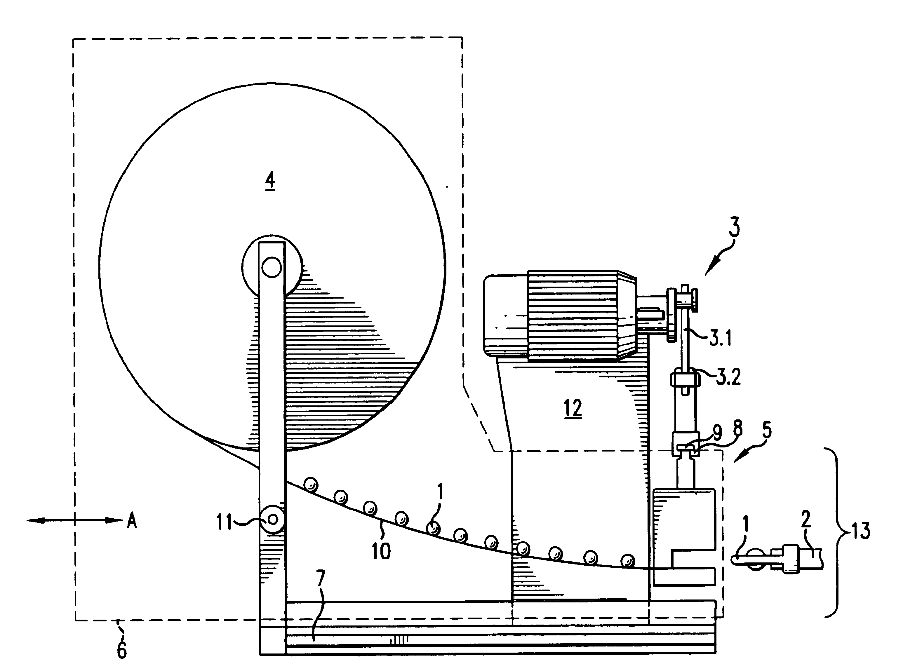
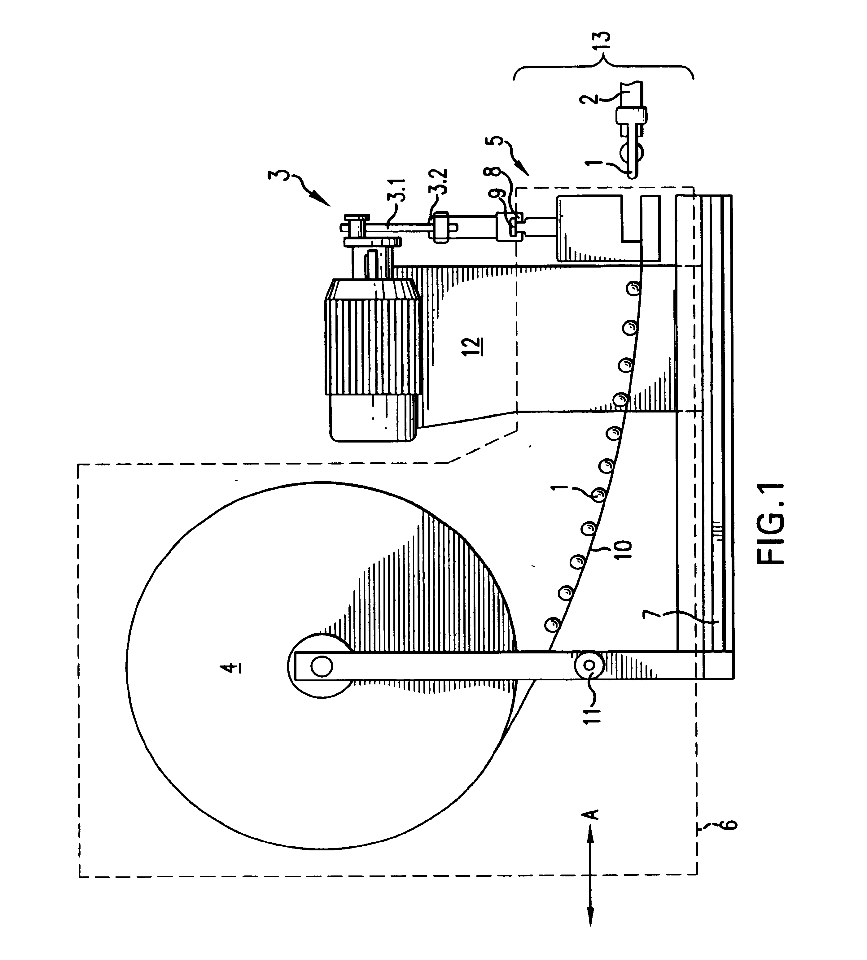
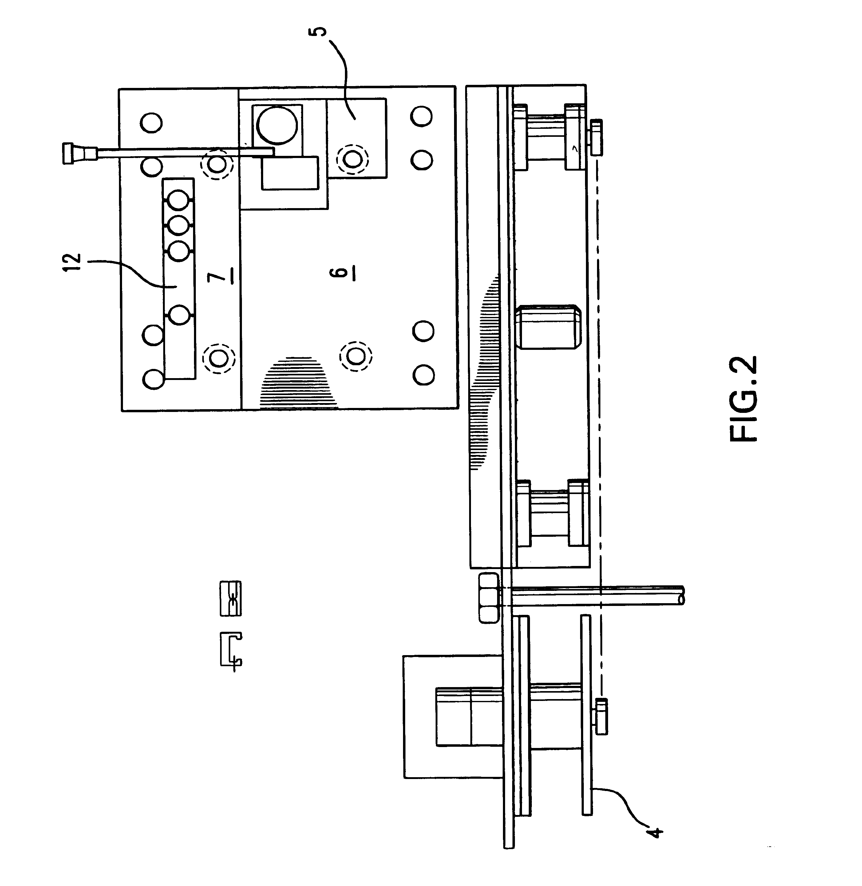
In the device according to the present invention, it is provided that at least the processing unit and the storage unit are configured as a self-enclosed assembly and that the assembly, as a self-enclosed unit, can be separated from the drive unit. As a result, adaptation tasks that may be necessary can be performed outside the device itself. In this way, the device can remain in use until the replacement process is carried out, it being then switched off for a short time to replace the assembly and immediately thereafter placed once again in oper...


PUM

PropertyMeasurementUnit
Distanceaaaaaaaaaa
Transport propertiesaaaaaaaaaa
Proximity effectaaaaaaaaaa

Abstract

A device for the semi- or fully automatic attaching of a contact element (1) to a cable end (2), including a drive unit (3), a storage unit (4) containing a plurality of contact elements (1), a transport device for feeding contact elements (1) to the cable end (2), and a processing unit (5). At least the processing unit (5) and the storage unit (4) are configured as a self-enclosed assembly (6), which, as a self-enclosed unit, can be separated from the drive unit (3).

Description

The invention relates to a device for the semi- or fully automatic attaching of a contact element to a cable end, including a drive unit, a storage unit containing a plurality of contact elements, a transport device for feeding the contact elements to the cable end, and a processing unit.BACKGROUND INFORMATIONA device of this type is known. The drive unit, the transport device, and the processing unit, in this context, constitute a self-enclosed assembly that is specially refitted to adapt to the specific cable end being processed. In this context, the result is significant operating interruptions of the device. From an economic point of view, this is not satisfactory.DESCRIPTION OF THE INVENTIONThe invention is based on the objective of refining a device of this type such that the result is significantly reduced refitting times for the adaptation to cable ends being processed using contact elements that are different from each otherThis objective is achieved according to the presen...

Claims


Application Information

Patent Timeline
IPC IPC(8): H01R43/055H01R43/04
CPCH01R43/055Y10T29/49181Y10T29/49185Y10T29/53243Y10T29/5193Y10T29/53213Y10T29/53226Y10T29/53235
Inventor WOLL, MATTHIAS
Owner CARL FREUDENBERG KG
Why Eureka
Try Eureka