Manual control device, control and operating unit including a manual control device, and work machine or construction machine

a technology of manual control device and control and operating unit, which is applied in the direction of mechanical control device, controlling member, limiting/preventing/returning movement of parts, etc., can solve the problems of reducing the lifetime of the actuating unit or the requirement, complicated setup and the exposure of the manual control device to the most adverse environmental conditions

Active Publication Date: 2019-05-14
MOBA MOBILE AUTOMATION
View PDF27 Cites 0 Cited by
  • Summary
  • Abstract
  • Description
  • Claims
  • Application Information

AI Technical Summary

Benefits of technology

[0018]The inventive approach is of advantage compared to the approaches from the known technology since it is not required to provide an additional sensor element for acquiring the additional movement of the actuating element, for example in the vertical direction or z-direction. The invention has recognized that a movement in the vertical direction or z-direction may be acquired by the sensor signals already existing, since a movement of the actuating element comprising the magnetic position element, in a z-direction, results in a change in the magnetic field, more precisely in a change in the intensity of the magnetic field acquired and, consequently, in a change in intensity of the signal output by the sensor. This change in intensity is made use of according to the invention in order to detect a position of the actuating element along the z-axis. This procedure is of additional advantage in that the control unit or evaluating unit necessitated for evaluation only has to evaluate the signals obtained from the magnetic field sensor anyway, that is no additional circuit expenditure is necessary with regard to evaluating signals from other sensors. The actual evaluation is additionally of advantage in that it is easy to implement, since only the intensity of the signals present anyway is examined, which is possible at little expenditure as regards circuit technology, such that the signals indicating a deflection of the actuating element in the z-direction may be generated easily at the same time from the signals present anyway. In addition, all of the elements for acquiring the position are arranged within the evaluating unit and consequently protected from environmental influences.
[0027]Another advantage of this implementation is that deviations when mounting the actuating unit may also be tolerated. As has already been mentioned above in connection with known manual control devices, the actuating unit may be replaced independently of the sensor unit. Actually, the actuating unit is exposed to environmental conditions, whereas the sensor unit and the evaluation elements contained therein may be arranged in a casing so as to be protected from the environment such that the actuating unit is exposed to a stronger stress and a stronger wear and consequently has to be replaced more frequently. When replacing the actuating unit of the manual control device, the newly to mount actuating unit may be oriented obliquely compared to the actuating unit installed before, for example due to dirt, such that the zero point positions of the old and the new actuating unit no longer match. In such a case, calibration is nevertheless allowed, provided the deviation due to the variation when mounting is within the predetermined region around the actual zero point.
[0035]Advantageously, the manually unlatchable locking device is effective so that, in its non-actuated state, the non-tapering part of the rod is arranged in the region of the holes such that one ball is partly arranged in a hole and partly extends in a recess in the guide such that a movement of the guide and, thus, of the actuating element, is impossible. In the actuated state of the manually unlatchable locking device, the tapering part of the rod is arranged in the region of the holes so that a ball is arranged partly in a hole and extends into the guide pipe such that movement of the guide and, thus, the actuating element is possible.
[0036]The locking device in accordance with the embodiments mentioned above is of advantage since undesired actuation or deflection of the actuating element of the actuating unit may be avoided, for example by an unintended contact while performing work operations on a lifting work platform which is equipped with the inventive manual control device. The inventive implementation of the manually unlatchable locking device is of advantage since no external elements are provided, rather mechanics arranged within the structure is provided which can be actuated by easy handling using one hand only such that the locking is released easily. Advantageously, it is provided for locking to the locked position to be biased such that, when releasing the locking device and when the actuation element returns to the zero state, automatic latching is performed. This implementation is of advantage since it is ensured by this that, with non-actuation of the actuation element, same will automatically be returned to the zero state and be latched there such that, when the user releases the actuation element, same will return to a defined state starting from which a further actuation of the work machine or construction machine may be performed, after being unlatched again.
[0038]This embodiment is of advantage compared to conventional embodiments of a bellows, since easy replacement of the bellows is made possible. Conventional approaches use a bellows that is basically frustoconical and becomes narrower from a lower end in the direction of an upper end of the actuation element. The result of this is that the actuation element has to be removed for replacement so that the bellows may be pulled off same downwards. As has already been mentioned above, the actuation element is exposed to the environmental conditions and thus subject to increased wear. The actuation element comprises the bellows mentioned above which, during movement of the actuation element of the actuating unit, is moved correspondingly such that this element is subject to an even stronger stress than the other elements of the actuating unit and consequently has to be replaced more frequently than the entire actuating unit. In addition, the material of the bellows is usually an elastic material which, due to the environmental conditions, such as, for example, rain, sun, changes of temperatures, is subject to increased wear which may result in the material to become rough and thus brittle, again necessitating replacement. As has been mentioned, conventional approaches necessitate the actuation element or the entire actuating unit to be disassembled so as to pull off the bellows. In accordance with the invention, this is avoided by implementing the bellows to be essentially cylindrical, more precisely of a cylindrical shape such that the upper diameter of the bellows and the lower diameter of the bellows are larger than the diameter of the element of the actuating unit projecting beyond the bellows. Thus, in the case of replacement, only the corresponding fixing of the bellows at the elements of the actuating unit is released and the bellows may then be simply pulled off upwards, without any other parts of the actuating unit having to be demounted. The new bellows is then similarly pulled over the elements of the actuating unit from above and fixed such that replacement, compared to conventional approaches, is considerably easier and less complicated.
[0040]This embodiment is of advantage since, when mounting an actuation device, for example due to a necessitated replacement caused by wear, it is ensured that the actuating unit may take only a single orientation, thereby ensuring correct acquisition of the position of the magnetic positional element in the actuating element when first mounting same.

Problems solved by technology

Thus, the manual control devices and the control and operating units are usually exposed to most adverse environmental conditions, for example rain, dust and extreme temperatures.
The implementation of manual control devices described above, including a way of vertical actuation of the joystick, however, is of disadvantage in that additional sensor technology is necessitated for acquiring the vertical movement, which, apart from necessitating the provision of an additional sensor, also makes the setup of the manual control device more complicated due to the additional space necessitated.
This results in a reduced lifetime of the actuating unit or in the requirement of protecting the sensor or using a sensor of higher quality.
The costs of the actuating unit which is replaced regularly are increased by this.
In reality, situations may arise in which the manual control device is deflected undesirably.
When calibration is performed automatically when switching on the construction machine or providing the manual control device with power, this undesired deflection of the actuation element of the manual control device results in an erroneous calibration, which in turn does not allow proper operation.
Such a situation may, for example, arise when the control and operating unit of the work machine or construction machine has been covered during non-operation such that, for example, the cover acts on the manual control device and undesirably deflects same from the zero point.
Such an unsymmetrical orientation may, for example, arise when, when mounting the actuating unit, the actuating unit is installed to be somewhat tilted or oblique relative to the original mounting position, due to dirt or the like.
As has already been mentioned above, the actuation element is exposed to the environmental conditions and thus subject to increased wear.
In addition, the material of the bellows is usually an elastic material which, due to the environmental conditions, such as, for example, rain, sun, changes of temperatures, is subject to increased wear which may result in the material to become rough and thus brittle, again necessitating replacement.

Method used


Image

  • Manual control device, control and operating unit including a manual control device, and work machine or construction machine
  • Manual control device, control and operating unit including a manual control device, and work machine or construction machine
  • Manual control device, control and operating unit including a manual control device, and work machine or construction machine

Examples


Embodiment Construction

[0064]Embodiments of the present invention will be detailed below referring to the appended drawings, wherein same elements or elements of same effect are provided with same reference numerals in the appended drawings.

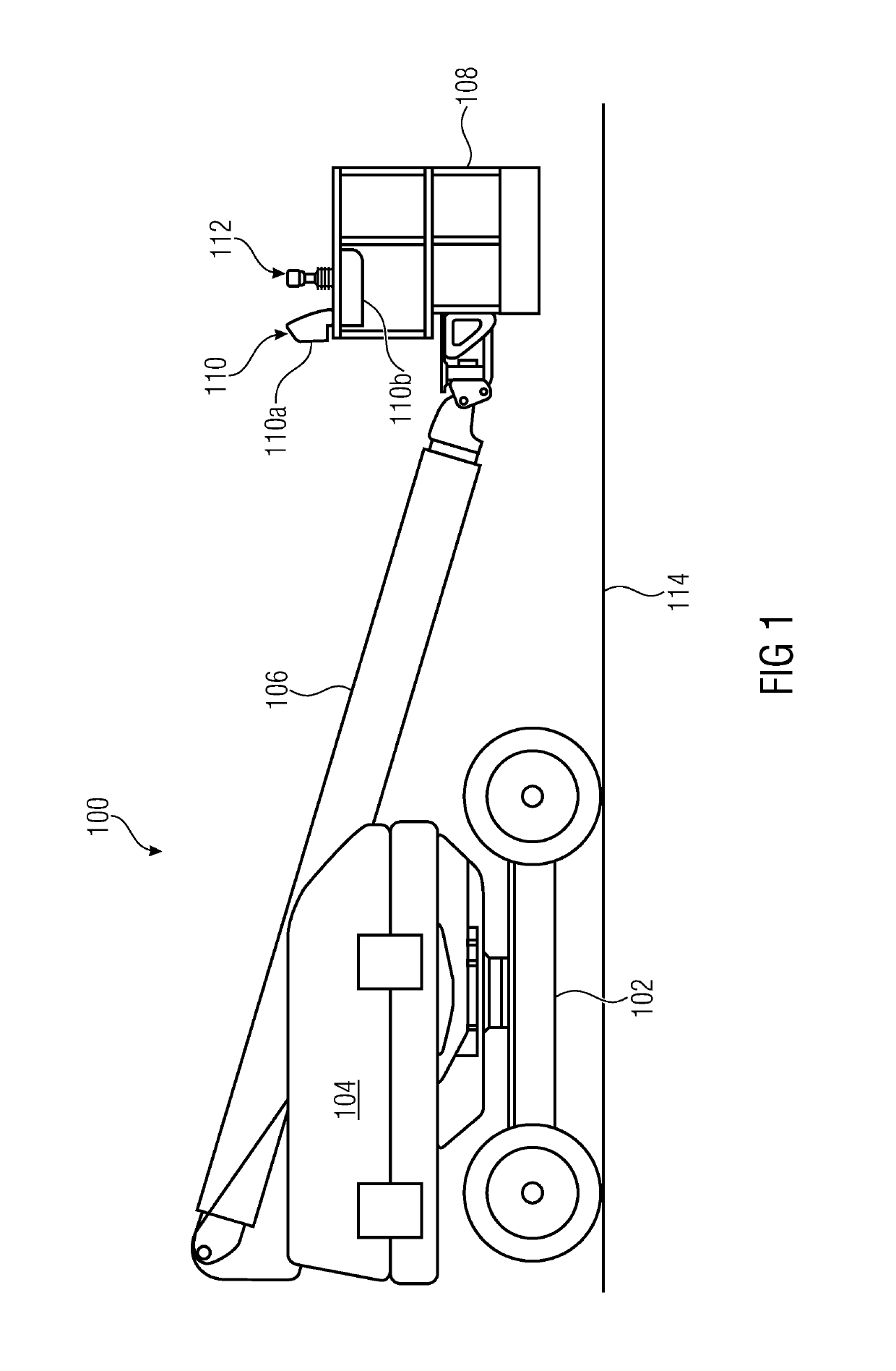
[0065]FIG. 1 shows the illustration of a work machine or construction machine which comprises a control and operating unit comprising the inventive manual control device. FIG. 1 shows a lifting work platform 100 including a movable chassis 102 and as assembly 104 rotatably arranged on the chassis 102 which, apart from the necessitated motors for moving the lifting work platform 100, comprises a crane mechanism 106 at the front end of which an operating platform, such as, for example, a work cage, is arranged. The work cage 108 comprises a control and operating unit 110 which in turn comprises a first casing part 110a which is basically oriented vertically, and a second casing part 110b. The control unit 110 additionally comprises a manual control device 112 which will ...


PUM


Abstract

A manual control device for a control and operating unit of a lifting work platform, work machine or construction machine has at least one actuating unit which has an actuation element having at least one magnetic position element, and an evaluating unit having at least one magnetic field sensor unit. The evaluating unit is configured to detect a position and / or movement of the actuation element in a plane of movement based on a sensor signal from the magnetic field sensor unit. The actuation element is movable relative to the sensor unit along a further direction of movement perpendicularly to the plane of movement, wherein the evaluating unit is configured to detect a movement of the actuation element along the further direction of movement based on a sensor signal from the magnetic field sensor unit.

Description

CROSS-REFERENCE TO RELATED APPLICATION[0001]This application claims priority from European Application No. EP15164311.1, which was filed on Apr. 20, 2015, and is incorporated herein by reference in its entirety.BACKGROUND OF THE INVENTION[0002]The present invention relates to a manual control device for a control and operating unit which is employed in the field of work machines, for example mobile work machines, or construction machines.[0003]Such manual control devices are used as control and operating units in mobile work machines or construction machines, for example for moving a work cage of a lifting work platform or for adjusting a work tool of a construction machine. Thus, the manual control devices and the control and operating units are usually exposed to most adverse environmental conditions, for example rain, dust and extreme temperatures.[0004]DE 20 2010 004 128 U1 describes a manual control device including separate actuation and evaluation, which basically consists of...

Claims


Application Information

Patent Timeline
Patent Type & Authority Patents(United States)
IPC IPC(8): G05G5/02G05G5/08G01D5/14G05G9/047G05G1/04G05G5/04G05G1/06
CPCG05G5/02G01D5/145G05G1/04G05G1/06G05G5/08G05G9/047G05G5/04G05G2009/04777G05G2009/04755G01D5/12G05G2009/04711G01D2205/95
Inventor ZILS, BORISKUEHR, THOMASTROST, KARL-FRIEDRICH
Owner MOBA MOBILE AUTOMATION
Why Eureka
Try Eureka