Preferential deflection hinge mechanism with an idler for foldable portable electronic devices

a portable electronic device and hinge mechanism technology, applied in the field of hinge clutches, can solve the problems of inability to operate well before the intended cycle, difficulty in inserting the hinge mechanism within the body of the phone, and inability to accept the wear of the hinge housing,

Inactive Publication Date: 2004-07-20
QUALCOMM INC
View PDF6 Cites 46 Cited by
  • Summary
  • Abstract
  • Description
  • Claims
  • Application Information

AI Technical Summary

Problems solved by technology

Unfortunately, such movement will often cause unacceptable wear on the hinge housing.
Because the housing and components are often made of lightweight and non-durable materials such as ABS or ABS-PC plastic, they often fail well before operating the intended cycles.
In addition, the difficulty of inserting the hinge mechanism within the body of the phone may require special tools and procedures.
As a consequence, when one of the hinge components fails, the entire assembly is usually discarded and replaced.
Due to the possibility of premature failure, many conventional electronic devices require separate clutch housings for each point of attachment between the housing and the foldable lid.
Unfortunately, the need for an additional clutch housing has many shortcomings.
The additional clutch housing must be manufactured from durable, relatively expensive materials, which are often unsuitable for very thin-walled designs and are difficult to color.
As a result, face cam clutches that employ an additional housing are often excessively bulky and relatively expensive.
The requisite tolerances represent addition design and manufacturing costs.
Unfortunately, the hinge clutch mechanism when rotated may pinch and even cut such wires, causing failure of the lid-mounted component.

Method used


Image

  • Preferential deflection hinge mechanism with an idler for foldable portable electronic devices
  • Preferential deflection hinge mechanism with an idler for foldable portable electronic devices
  • Preferential deflection hinge mechanism with an idler for foldable portable electronic devices

Examples


Embodiment Construction

While the present invention is described herein with reference to illustrative embodiments for particular applications, it should be understood that the invention is not limited thereto. Those having ordinary skill in the art and access to the teachings provided herein will recognize additional modifications, applications, and embodiments within the scope thereof and additional fields in which the present invention would be of significant utility.

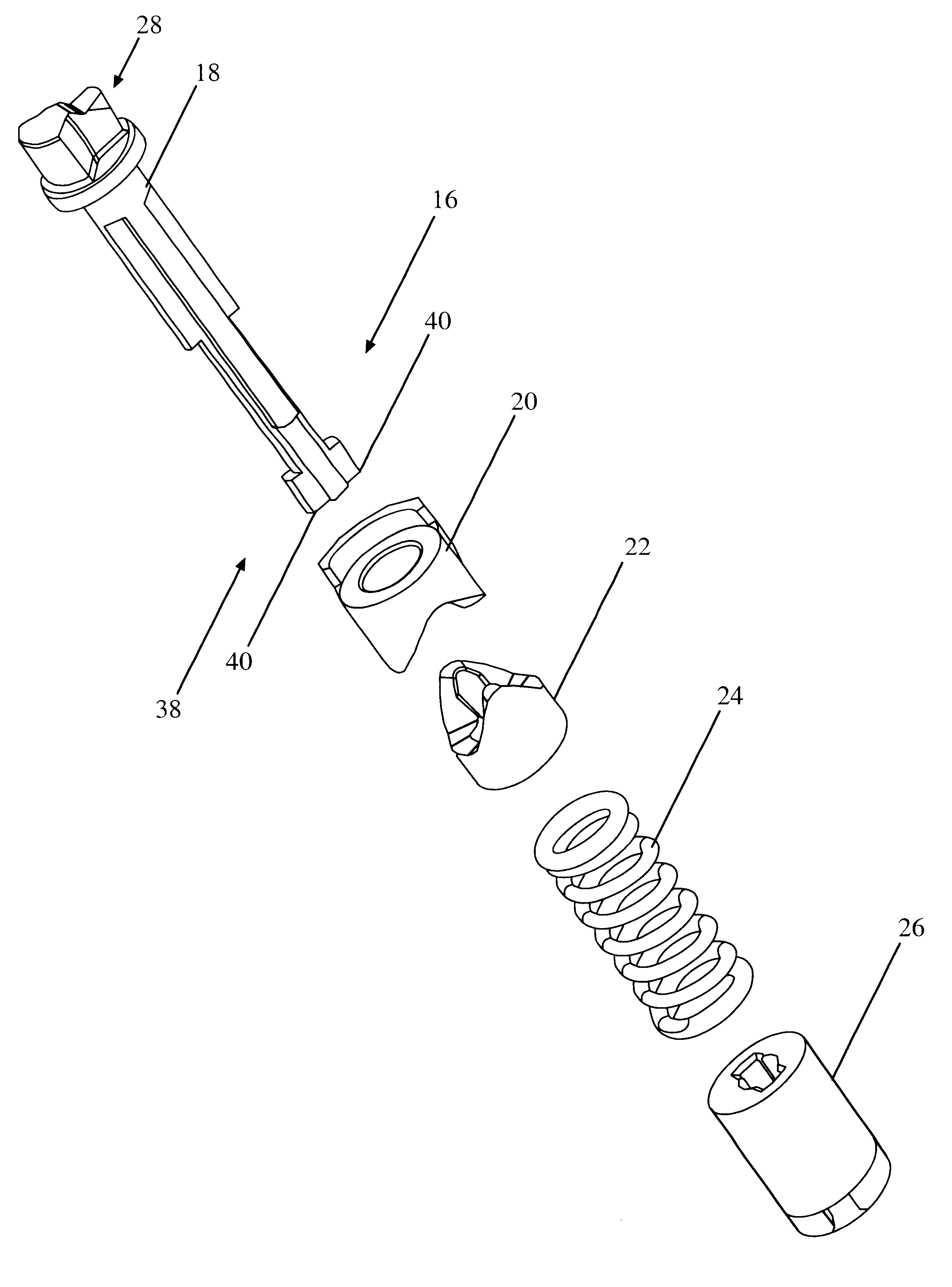
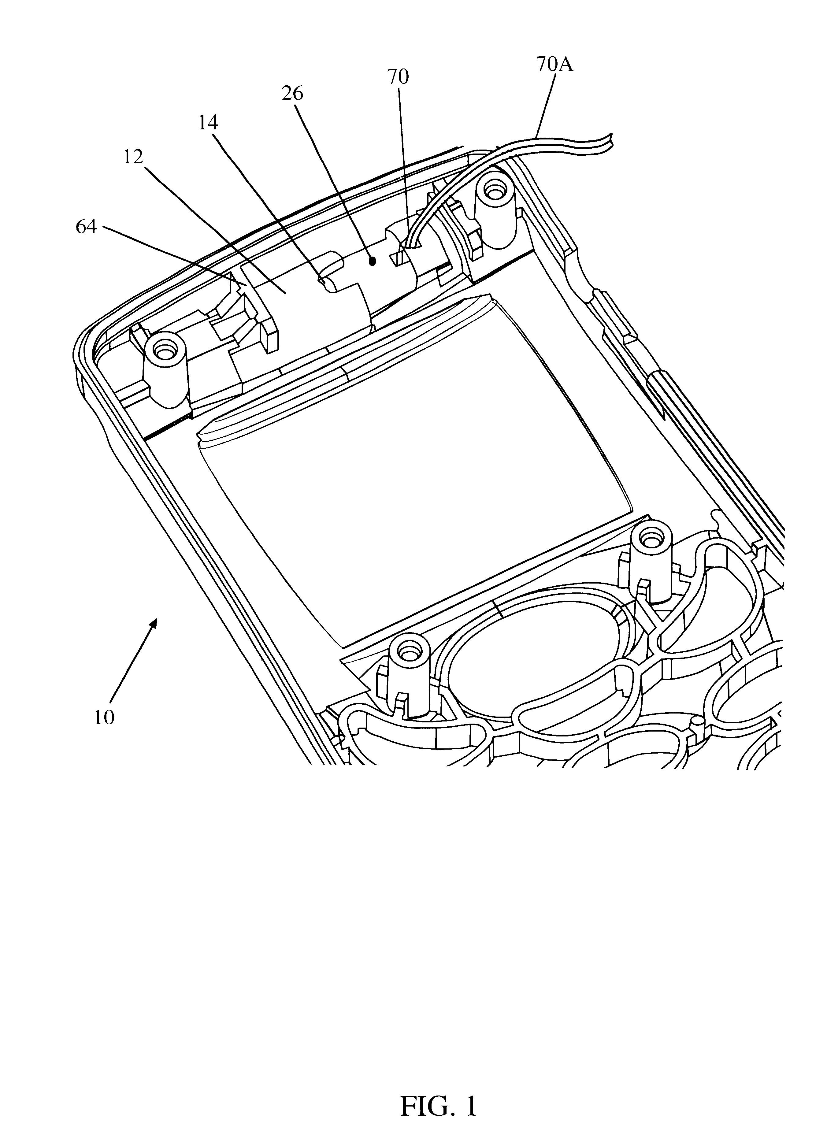
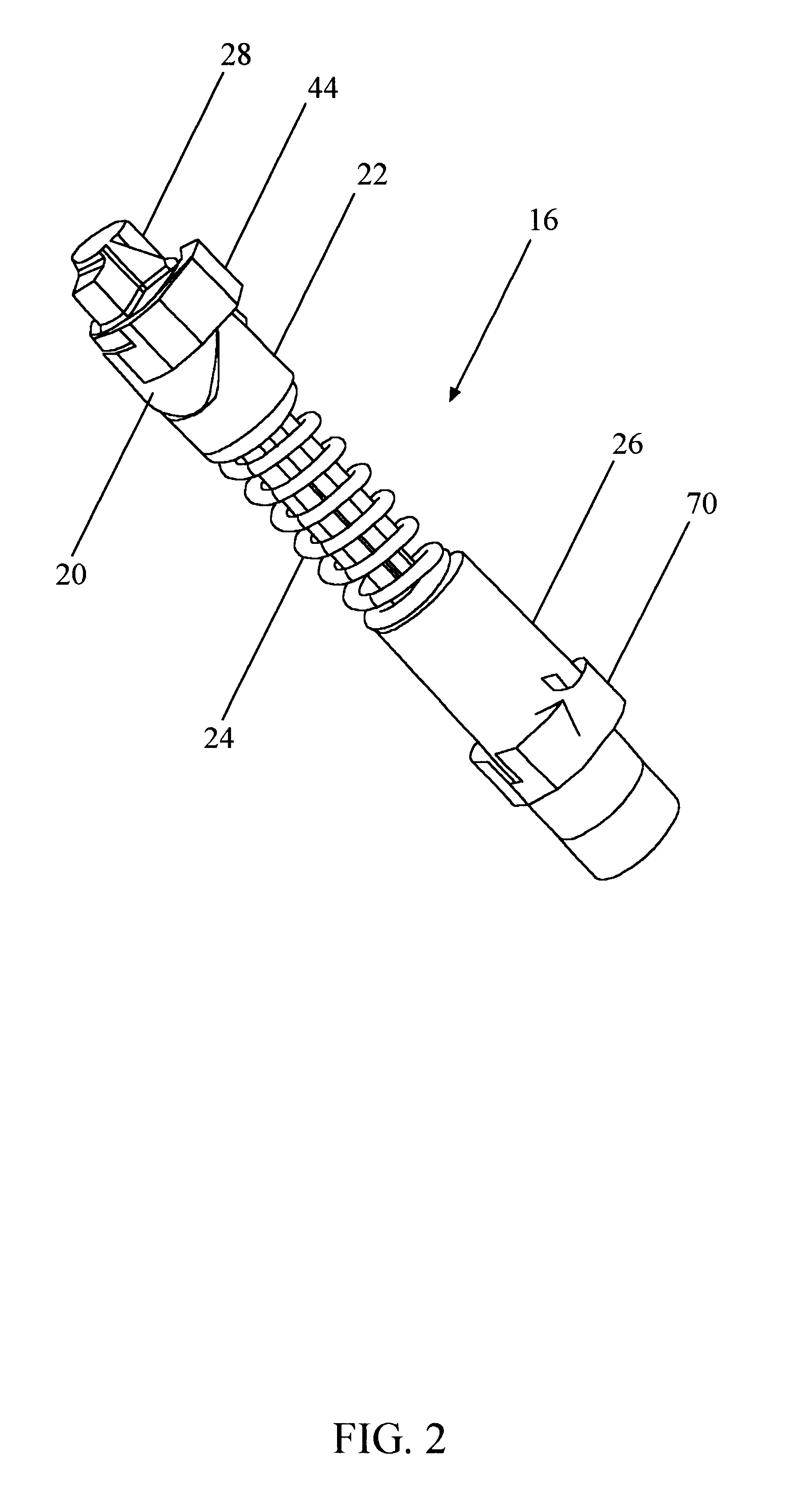
FIG. 1 is a partial view of the housing 10 of an electronic device, which may, for purposes of the following discussion, take the form of a body of a flip phone assembly. Housing 10 may be formed of molded plastic or formed / cast metal and include a hollow, sleeve-shaped portion 12 with an indentation 14 formed on the surface thereof. As will be explained below, a hinge clutch mechanism 16 formed in accordance with the present invention is shown in FIG. 2. The mechanism is specifically designed to be inserted within housing 10 with a portion...


PUM


Abstract

A space efficient and cost effective hinge clutch mechanism for facilitating the rotational positioning of a lid member of a portable electronic device relative to the housing the device. The clutch mechanism includes an elongated cam-shaft extending through a plurality of aligned components including a face cam member, a cam follower, and a compression spring and partially through a hollow retaining member. Rotation of the retaining member prevents the cam-shaft from being inadvertently with drawn. The clutch mechanism may be manually or automatically pre-assembled before insertion into the housing. An idler positioned adjacent to the retaining member serves as conduit for wires extending from the rotating lid member and the housing of the portable electronic device. The interaction of the cam and cam follower retains the lid in its fully open or fully closed positions until sufficient rotational force is exerted on the lid to overcome the tangential force of the spring.

Description

1. Field of the InventionThis present invention relates to portable electronic devices. More specifically, the present invention relates to hinge clutches employed in portable electronic devices.2. Description of the Related ArtPortable electronic devices have gained universal acceptance in a variety of applications including, but not limited to, wireless phones, laptop and palmtop computers, cameras as well as entertainment devices. Such applications usually demand durable, lightweight, space-efficient, and ultimately cost effective devices and associated components.Many portable electronic devices, such as common flip-phones, employ a body member and a separate, foldable lid. The foldable lid is rotationally supported by and attached to the body of the device via at least one clutch hinge mechanism. The clutch hinge allows for manual rotation of the lid from a closed position adjacent the body of the phone to an angular position relative to the phone body to facilitate use of the ...

Claims


Application Information

Patent Timeline
Patent Type & Authority Patents(United States)
IPC IPC(8): E05D11/00E05D11/10H04M1/02
CPCH04M1/0216E05D11/1078E05Y2900/606
Inventor DORAISWAMY, SUNDARRAJSANTOS, THEODORE R.LARSON, DAVID
Owner QUALCOMM INC
Why Eureka
Try Eureka