Pulley assembly

a technology of pulleys and components, applied in the direction of gearing control, portability lifting, couplings, etc., can solve the problems of limited working life, wear, and additional stress on the bushings

Active Publication Date: 2012-06-19
DAYCO EURO
View PDF29 Cites 25 Cited by
  • Summary
  • Abstract
  • Description
  • Claims
  • Application Information

AI Technical Summary

Benefits of technology

[0009]The object of the present invention is achieved by a pulley assembly as defined in claim 1.

Problems solved by technology

In the known pulley assemblies, the resultant of the radial pressures acting between the second end portion of the spring and the cylindrical wall causes an additional stress on the bushing which tends to wear out and have a limited working life.

Method used


Image

  • Pulley assembly
  • Pulley assembly
  • Pulley assembly

Examples


Embodiment Construction

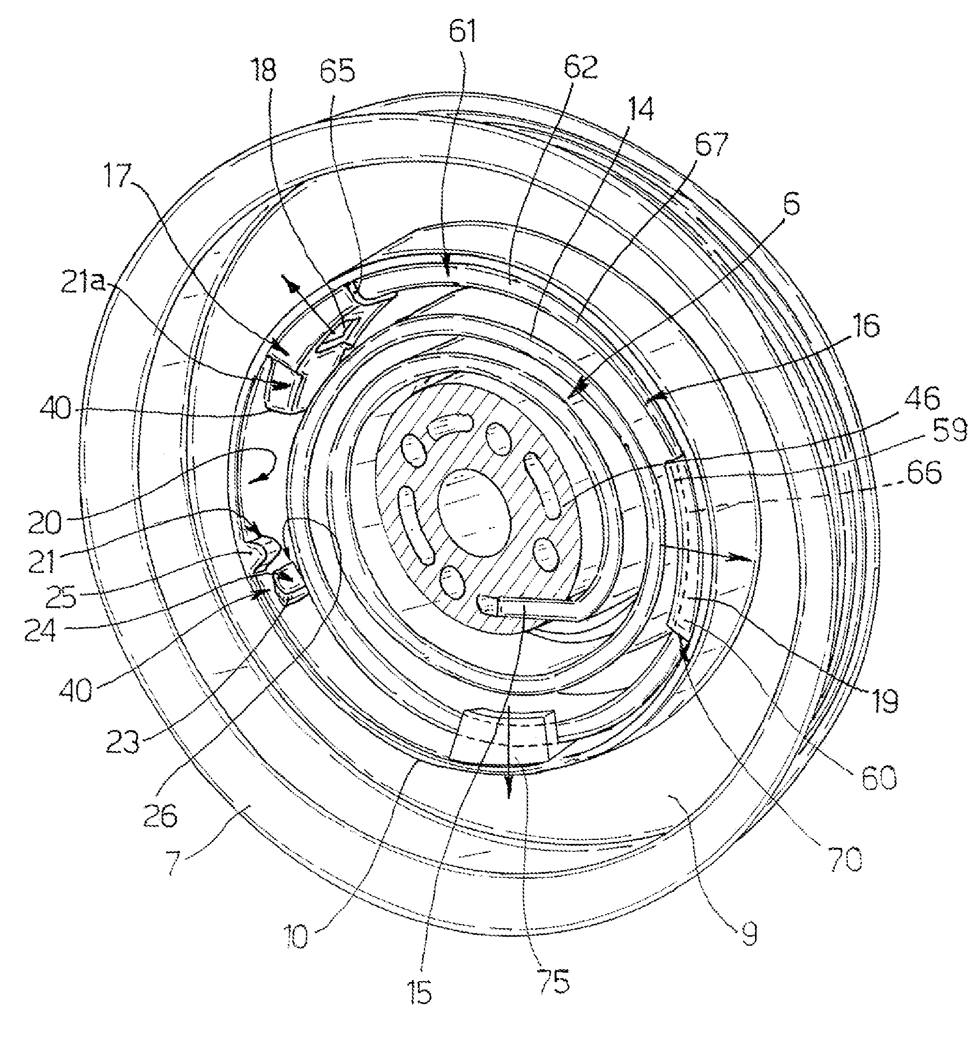
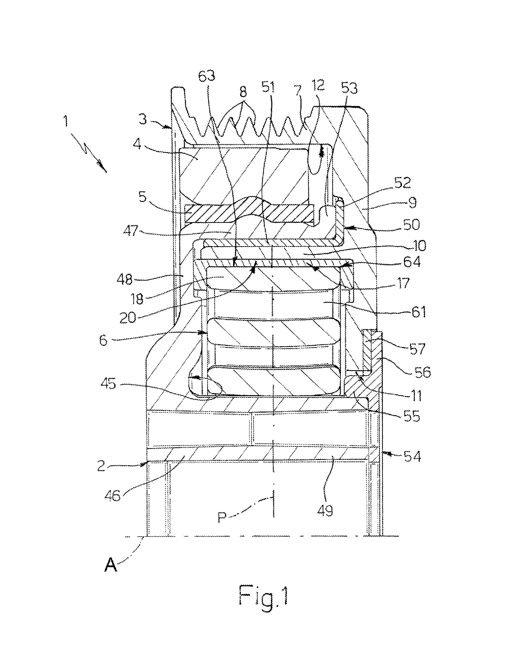
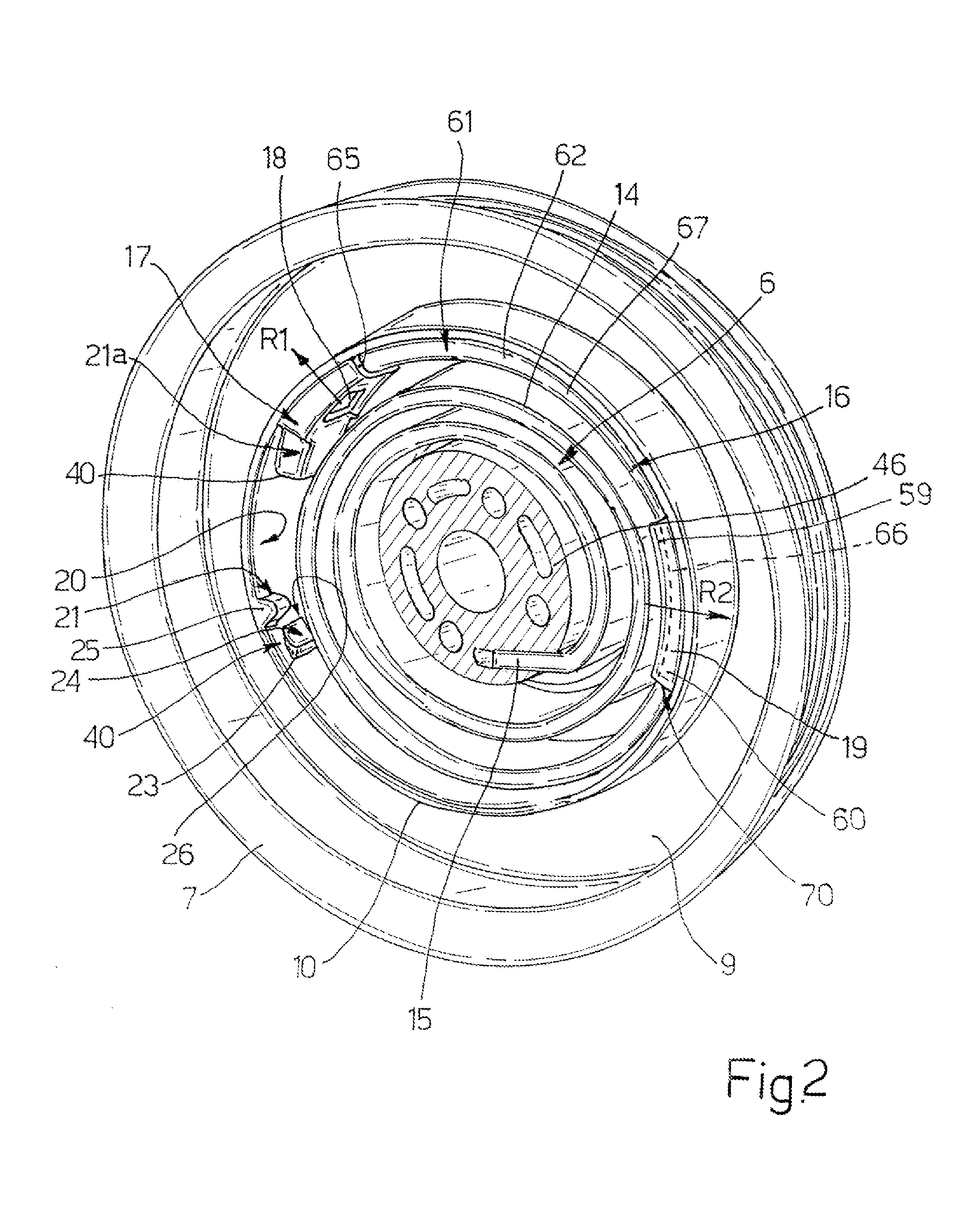
[0020]In FIG. 1, number 1 indicates as a whole a pulley assembly comprising a hub 2 adapted to be rigidly connected to a crankshaft of an internal combustion engine, a pulley 3 radially supported by hub 2, a seismic mass 4 connected to hub 2 by means of a band 5 of elastomeric material for defining a torsional vibration dynamic damper, and a spiral spring 6 for rotationally connecting hub 2 to pulley 3.

[0021]In particular, hub 2 defines an annular cavity 45 and integrally comprises a tubular element 46 having an axis A, a side wall 48 radially protruding from tubular element 46 and a cylindrical wall 47 radially external to tubular element 45.

[0022]Pulley 3 is preferably made of a single piece and comprises a crown 7 coaxial to axis A and defining a plurality of grooves 8 adapted to cooperate with a belt (not shown) of an accessory drive, a side wall 9 perpendicular to axis A and protruding from a side of crown 7 toward axis A, and a cylindrical wall 10 protruding from side wall 9 u...


PUM


Abstract

A pulley assembly for flexible motor vehicle transmission, comprising a supporting member rotatable about an axis, a pulley adapted to cooperate with a belt and connected to the supporting member to be rotatable about said axis with respect to the supporting member, a spiral spring interposed between the supporting element and the pulley and comprising a sliding portion elastically loaded in radial direction against a sliding wall carried by one of either the supporting members or the pulley for coupling by a tangential force transmission the hub to the supporting member. In particular, the sliding portion defines a first contact zone and a second contact zone in which is concentrated the contact pressure exchanged between the sliding portion and the sliding wall, the first and second contact zone being reciprocally and angularly distanced.

Description

TECHNICAL FIELD[0001]The present invention relates to a pulley assembly, particularly for a drive belt, adapted to connect a plurality of accessory members to a crankshaft of an internal combustion engine.BACKGROUND ART[0002]Pulley assemblies comprising a hub adapted to be rigidly connected to a crankshaft of an internal combustion engine and a pulley adapted to cooperate with a belt of the accessory drive and rotationally connect to the hub by means of a spiral spring are known.[0003]Such known assemblies also generally comprise an integrated torsional damper, which consists of an annular seismic mass coaxial to the hub and an elastic connection element arranged between the hub and the seismic mass.[0004]In use, the spiral spring is coupled with the rotation of the hub and the pulley and presents a relatively low stiffness so as to allow to filter the torsional vibrations of the crankshaft and avoid such vibrations from being transmitted to the accessory drive.[0005]In the known pu...

Claims


Application Information

Patent Timeline
Patent Type & Authority Patents(United States)
IPC IPC(8): F16D3/00F16H63/00F16H9/00F16H59/00F16H55/36F16H55/14F16H61/00
CPCF16D41/203F16F15/1213F16F15/1297F16F15/1442F16H55/36F16H2055/366
Inventor RIU, HERVE
Owner DAYCO EURO
Why Eureka
Try Eureka