Locking positional arm device

a positional arm and locking technology, applied in the direction of couplings, applications, surgical instruments supporting, etc., to achieve the effect of preventing the movement of the moveable obj

Inactive Publication Date: 2004-07-27
HOLBROOK DANA W
View PDF12 Cites 141 Cited by
  • Summary
  • Abstract
  • Description
  • Claims
  • Application Information

AI Technical Summary

Benefits of technology

It is also the objective of the invention to provide a device which may be used to anchor an object to a table, desk, ladder or work area in a fixed position, the object being held in such fixed position until released from the device. Dep

Problems solved by technology

However, none of them include a thumb activated piston rod assembly that lockingly engag

Method used


Image

  • Locking positional arm device
  • Locking positional arm device
  • Locking positional arm device

Examples


Embodiment Construction

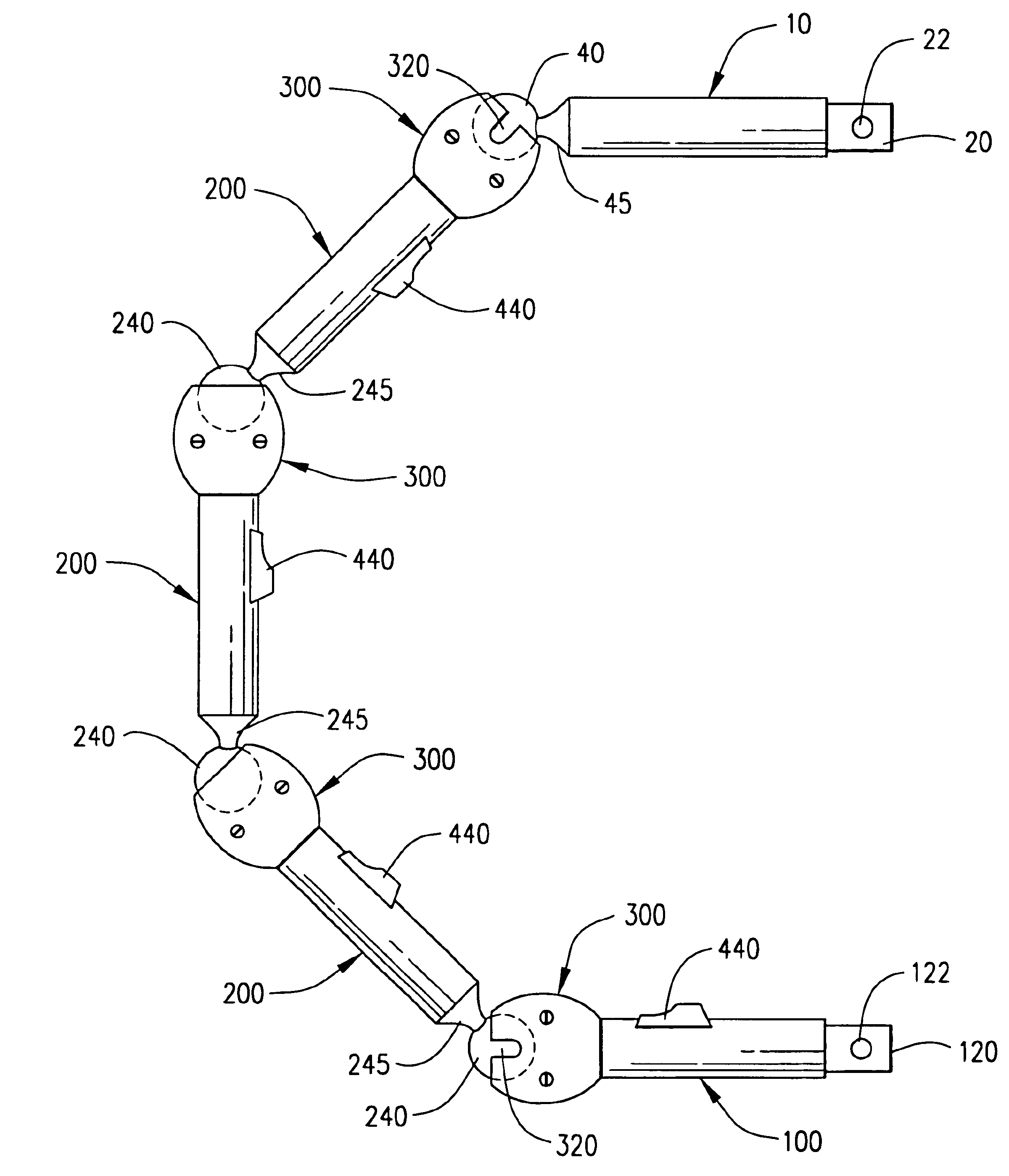
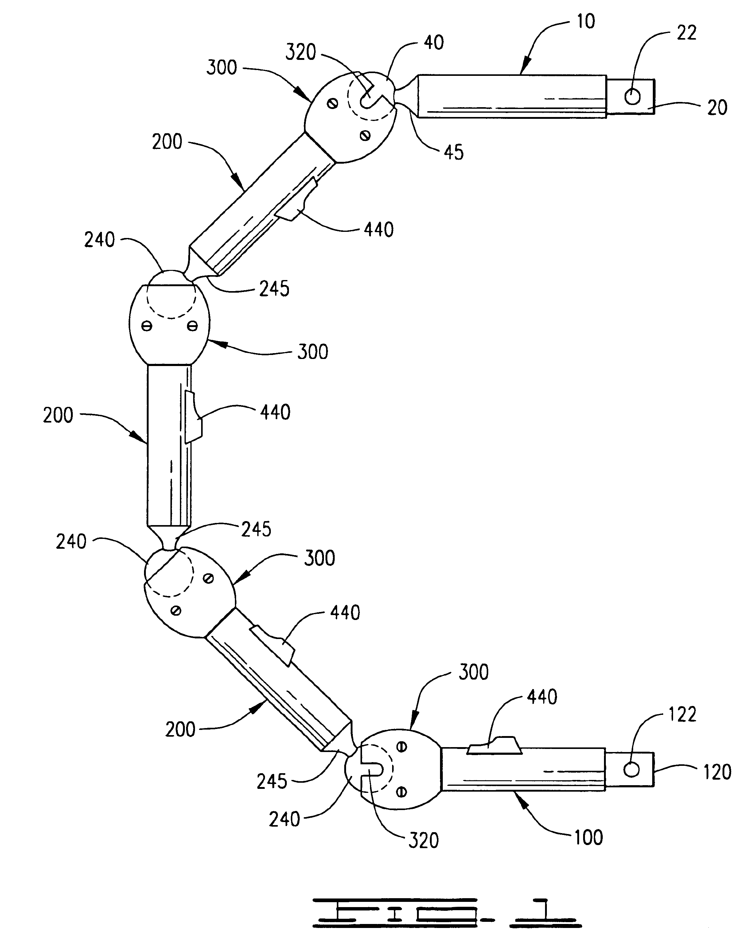
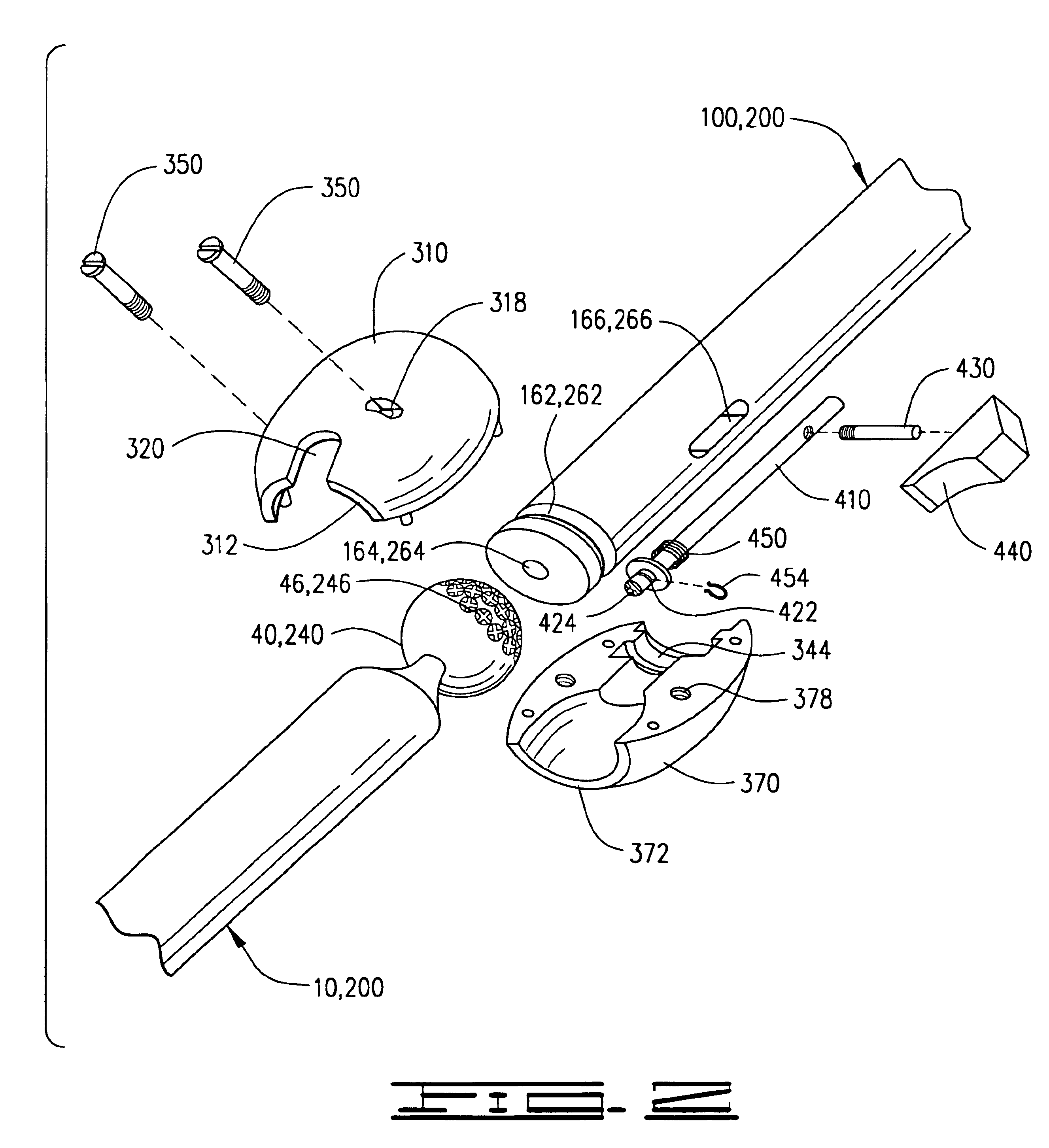
A multiple adjusting support arm device, shown in FIGS. 1-9 of the drawings, attaches to two locking tools, providing an adjustable connecting arm for supporting the locking tools in a fixed position, the arm device comprising essentially a terminal sphere rod 10, FIG. 5, having a tool connecting terminal end 20, a body 30 and a sphere end 40, at least one intermediate rod 200, FIG. 6, having a sphere end 240, a body 230 and a housing end 260 forming a circular groove 262, a terminal housing rod 100, FIG. 7, having a tool connecting terminal end 120, a body 130, and housing end 160 forming a circular groove 162, a housing assembly 300, FIGS. 8a and 8b, having a first housing section 310 and a second housing section 370 attached together by screws 260, the housing assembly 300 forming a spherical cavity 360 and a circular rod engaging ridge 340, and a spring action locking piston assembly 400, FIG. 9 contained within the housing end 160, 260 of each intermediate rod 200 and terminal ...


PUM


Abstract

A positional arm device is a series of multiple rods connected to each other by a spherical housing and ball joint with a spring-loaded locking piston providing a multiple position holding device serving as an anchor to hold tools in a certain position, and also as a connector between two object where a certain secure fixed position between the two objects is desired. The arm device has a spherical terminal rod, a plurality of intermediate rods and a terminal housing rod connected together by a spherical housing adjustably positioned and locked by a spring-loaded piston shaft engaging a sphere end retained within the housing, the piston shaft lockingly engaging one of a multiplicity of grooved indentations on the surface of the sphere end.

Description

NoneI. BACKGROUND OF THE INVENTION1. Field of InventionA positional arm device is a series of multiple rods connected to each other by a spherical housing and ball joint with a spring-loaded locking piston providing a multiple position holding device serving as an anchor to hold tools in a certain position, and also as a connector between two object where a certain secure fixed position between the two objects is desired. The arm device has a spherical terminal rod, a plurality of intermediate rods and a terminal housing rod connected together by a spherical housing adjustably positioned and locked by a spring-loaded piston shaft engaging a sphere end retained within the housing, the piston shaft lockingly engaging one of a multiplicity of grooved indentations on the surface of the sphere end.2. Description of Prior ArtIt is recognized that numerous devices exist that provide a multiple positioning joint for support structures, including musical instrument stands, surgical support d...

Claims


Application Information

Patent Timeline
IPC IPC(8): F16C11/10F16C11/06F16C11/04F16M11/14F16M11/02A61B19/00
CPCA61B19/26F16C11/0604F16C11/10F16M11/14F16M11/2078F16M11/40Y10T403/32196Y10T403/32631Y10T403/32311Y10T403/32811Y10T403/32573Y10T403/32032F16M2200/024A61B90/50
Inventor HOLBROOK, DANA W.
Owner HOLBROOK DANA W
Why Eureka
Try Eureka