
Elbow prosthesis

a technology for elbows and prostheses, applied in the field of elbow prostheses, can solve the problems of premature wear of articulating surfaces, inducing parasitic movements, and considerable risk of dislocation or transverse instability

Inactive Publication Date: 2004-07-27
TORNIER SA SAINT ISMIER
View PDF20 Cites 117 Cited by
  • Summary
  • Abstract
  • Description
  • Claims
  • Application Information

AI Technical Summary

Benefits of technology

The design provides increased stability for transverse movements, reduces dislocation risks, and allows for anatomical adaptation, improving the overall functionality and safety of the elbow prosthesis by ensuring the axis of varus-valgus movement is within the ulnar component, enhancing transverse stability compared to existing sliding prostheses.

Problems solved by technology

To allow such a movement, the hinge must be provided with a considerable radial clearance, which leads to premature wear of the articulating surfaces.
Such prostheses allow transverse movements, but are unstable perpendicularly and / or parallel to the sagittal plane, hence there is a considerable risk of dislocation or transverse instability inducing parasitic movements when the elbow is flexed.

Method used


Image

  • Elbow prosthesis
  • Elbow prosthesis
  • Elbow prosthesis

Examples


Embodiment Construction

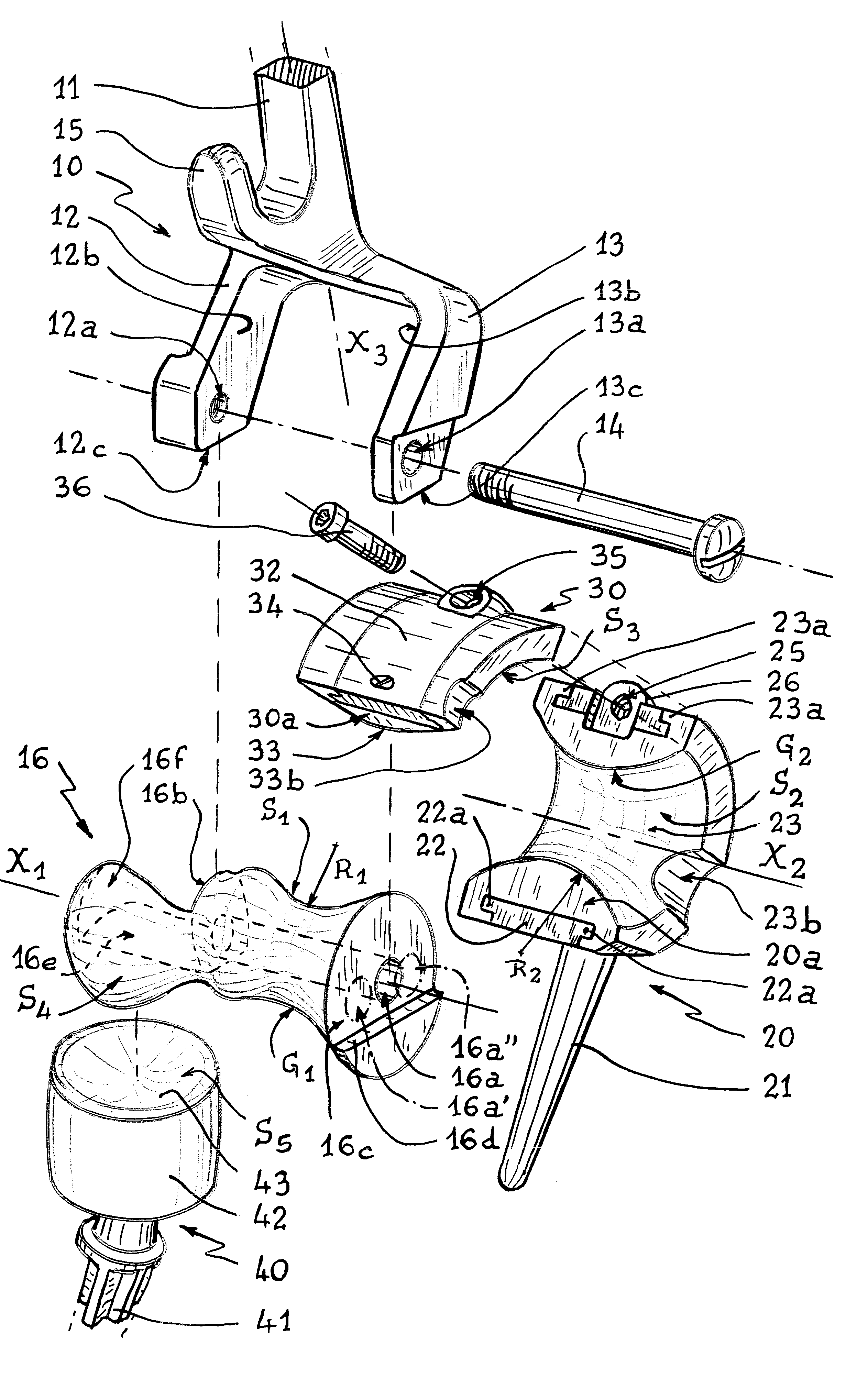
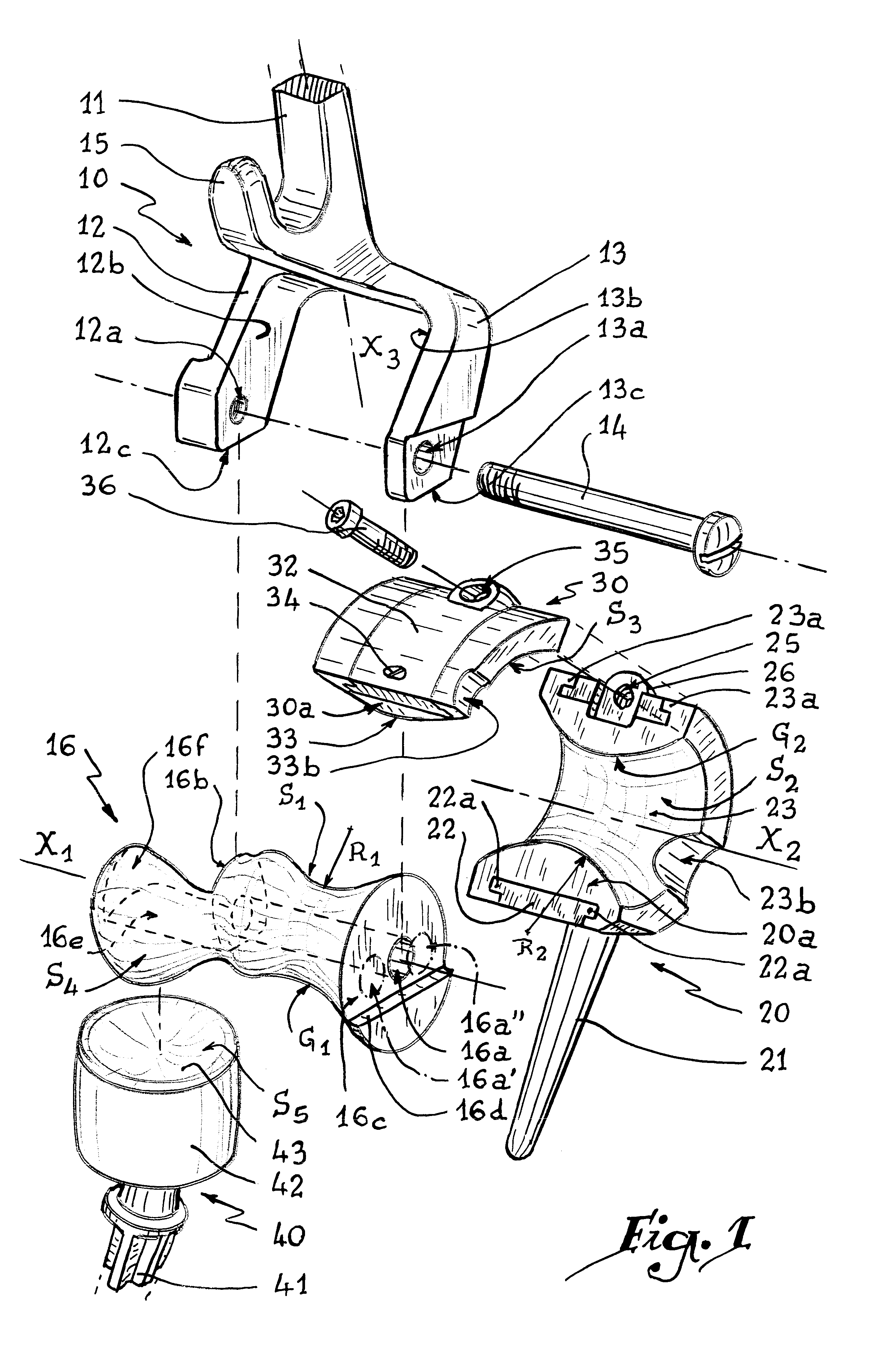
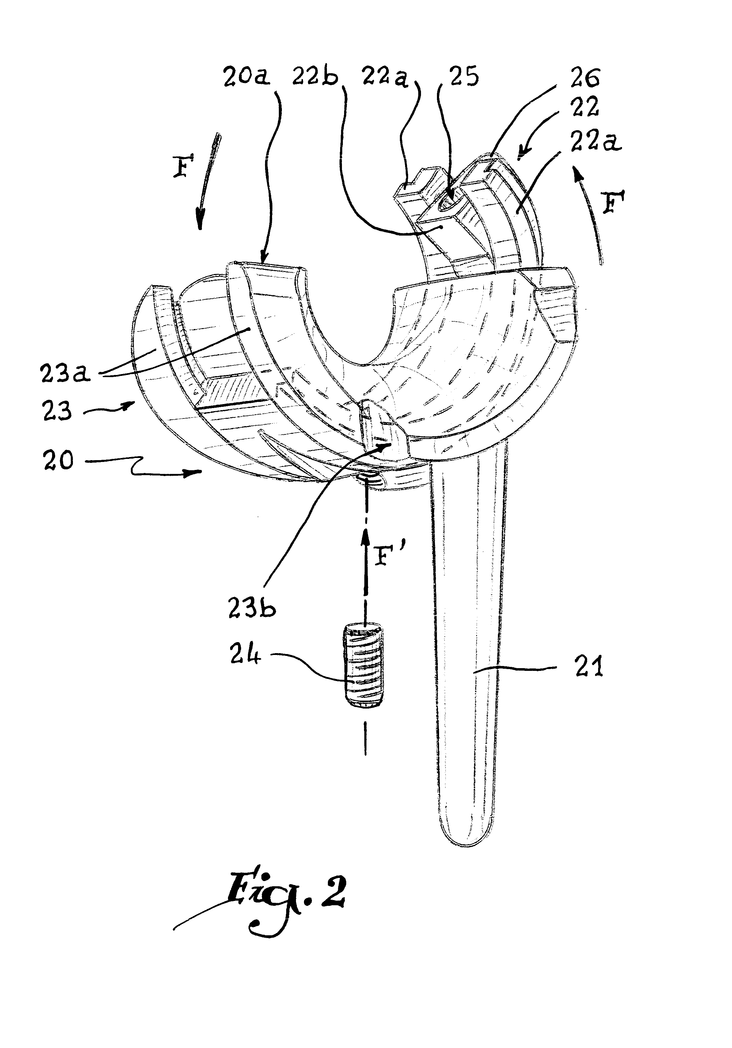
Referring now to the drawings, the prosthesis visible in FIGS. 1 to 6 comprises a humeral component 10 presenting a rod 11 intended to be driven in the medular channel of a humerus H and extending in two tabs 12 and 13 each pierced with an orifice 12a or 13a for passage of a screw 14 forming shaft. Orifice 12a is tapped, which enables it to cooperate with the outer threading of screw 14.

The rod 11 also extends in a third tab 15 intended to abut against the cortex of the humerus H and to prevent a possible forward tipping of the humeral rod.

An elongated piece 16 is provided with a central bore 16a whose dimensions allow it to receive the screw 14. Two end surfaces 16b and 16c of the piece 16 are provided to come respectively into contact with the opposite surfaces 12b and 13b of the tabs 12 and 13, while screw 14 traverses the orifices and bores 13a, 16a and 12a.

In this position shown in FIGS. 3 to 6, an end surface 13c of the tab 13 is in abutment against an end shoulder 16d of the ...


PUM


Abstract

An elbow prosthesis which includes a humeral component having a rod extending along a longitudinal axis and this component further includes a generally cylindrical body having a first articulating surface about which an ulnar component is pivotally mounted so as to pivot about a longitudinal axis of the body. A spacing between a plane extending through the longitudinal axis of the body and the longitudinal of the rod of the humeral component is selected to define a desirable spacing therebetween depending upon a patient's morphology.

Description

1. Field of the InventionThe present invention relates to an elbow prosthesis comprising at least one humeral component and one ulnar component.2. Background of the InventionAs a function of the articular clearance and of the mode of coupling the humeral and ulnar prosthetic elements together, two principal types of prostheses are distinguished:prostheses with hinge arrangements, in which a common hinge pin is introduced in aligned orifices provided on the humeral component and on the femoral component. Taking into account the mode of assembling these prostheses, the hinge pin which defines the articulating surface necessarily presents a rectilinear generatrix, which is substantially different from the natural articulating surface of the trochlea. These hinge arrangements present good stability and allow a rotation in the sagittal plane of the joint. However, they prevent transverse movements such as the varus-valgus movement or a movement of ulnar axial rotation. To allow such a mo...

Claims


Application Information

Patent Timeline
Patent Type & Authority Patents(United States)
IPC IPC(8): A61F2/38A61F2/00A61F2/30A61F2/02A61B17/06
CPCA61F2/3804A61B17/06166A61F2002/30153A61F2002/30354A61F2002/30367A61F2002/30369A61F2002/30372A61F2002/30383A61F2002/30401A61F2002/30405A61F2002/30433A61F2002/30434A61F2002/30507A61F2002/30537A61F2002/30604A61F2002/30616A61F2002/30624A61F2002/30688A61F2002/30772A61F2002/30774A61F2002/30797A61F2002/3082A61F2002/30878A61F2002/30879A61F2002/30975A61F2002/3809A61F2002/3813A61F2002/3822A61F2002/3827A61F2002/3831A61F2220/0025A61F2220/0033A61F2220/0041A61F2230/0019A61F2250/0004A61F2310/00011
Inventor TORNIER, ALAIN
Owner TORNIER SA SAINT ISMIER
Learn More