Screens for RF magnetic flux

a magnetic flux and screen technology, applied in shielding materials, electrical equipment, antennas, etc., can solve the problems of mri and related applications that cannot be applied in the field of screen for rf magnetic flux, and the approach is clearly impossibl

Inactive Publication Date: 2004-07-27
TELEFON AB LM ERICSSON (PUBL)
View PDF9 Cites 22 Cited by
  • Summary
  • Abstract
  • Description
  • Claims
  • Application Information

AI Technical Summary

Problems solved by technology

This approach tends to be costly, and often carries with it a weight penalty.
This approach is clearly impossible for MRI and related applications, where there are strong DC or low frequency magnetic fields: the magnetic material would simply be attracted to the DC magnet with such force as to destroy the original magnetic shell.

Method used


Image

  • Screens for RF magnetic flux
  • Screens for RF magnetic flux
  • Screens for RF magnetic flux

Examples


Embodiment Construction

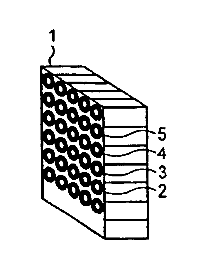
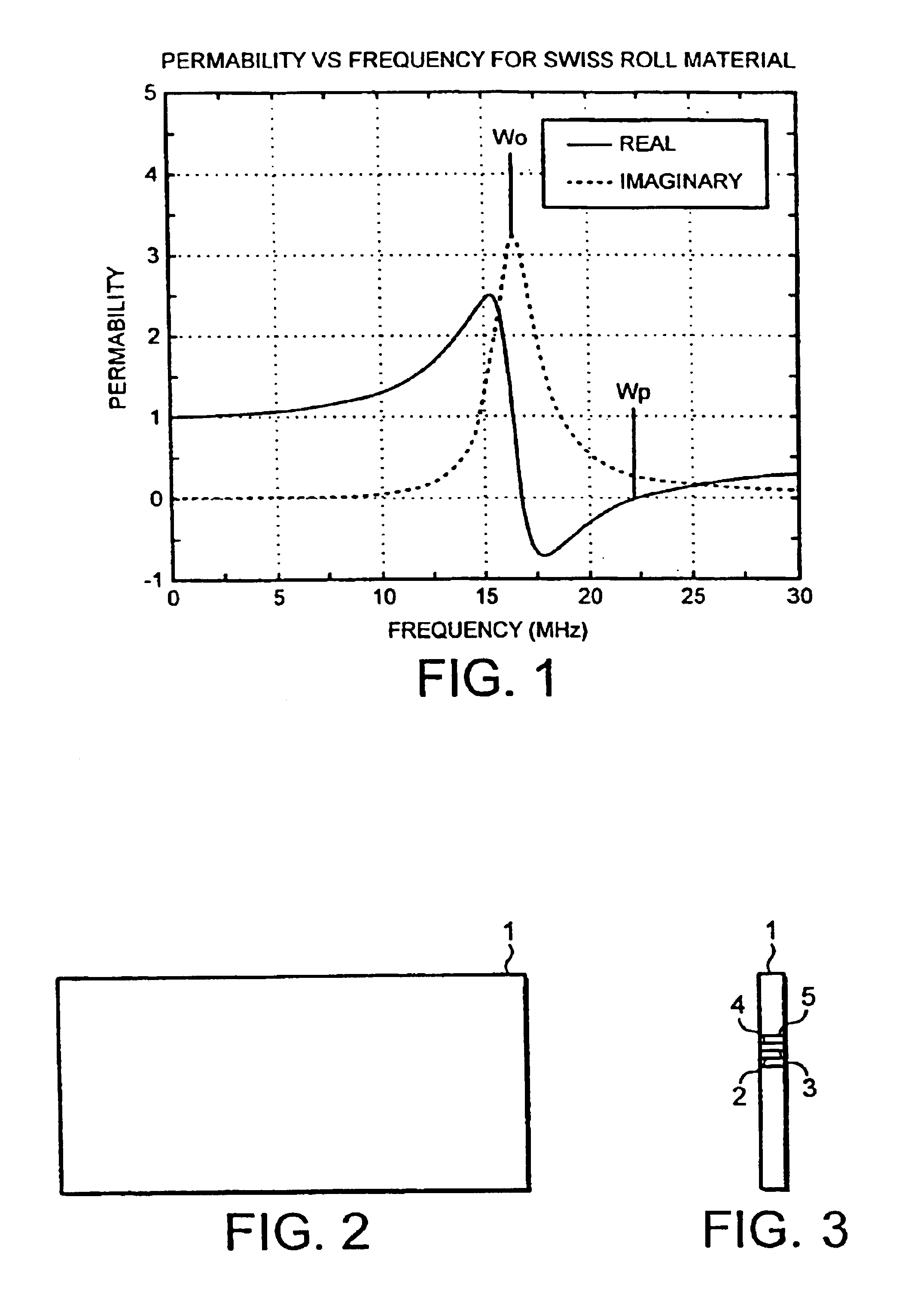
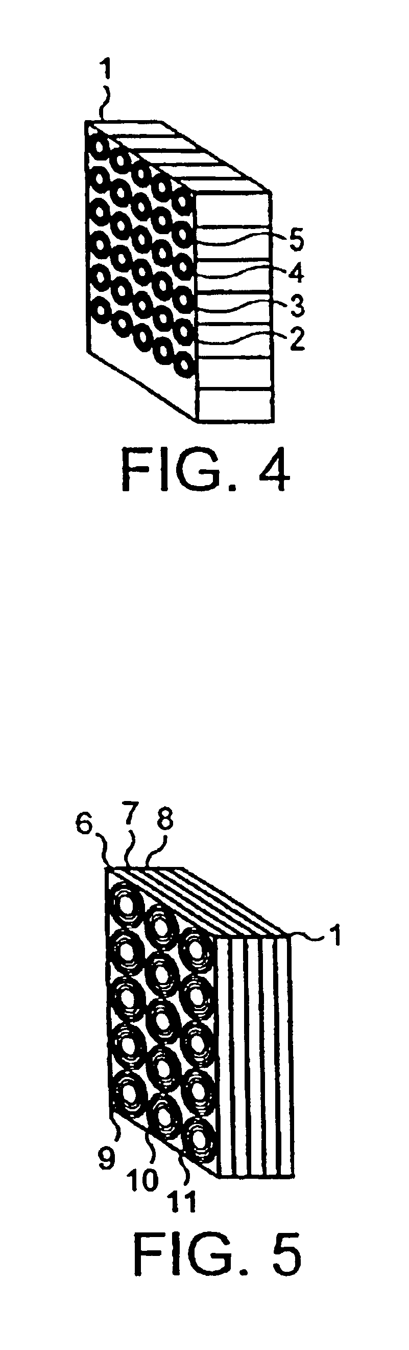
In one example of roll material such as is illustrated in FIGS. 3 and 4, the microstructured magnetic material consists of cylindrical elements, with each element being a "Swiss Roll". A switchable dielectric is incorporated between the layers, and this would reduce the resonant frequency so that the region with .mu.<0, which lies above the resonant frequency, was now at the operating frequency.

For ProFilm (Mylar base coated with 10 nm of aluminium and a glue layer to give a total film of about 50 .mu.m thickness, sheet resistance about 2.7 .OMEGA. / square), 50 turns are wound on an 8 mm mandrel giving an outside diameter of 12.6 mm, a resonant frequency of 22.0 MHz, a plasma frequency of 72.2 MHz, and a most negative value of magnetic permeability of .mu.=-2.1.

For Superinsulation (6.4 .mu.m thick Mylar with 50 nm aluminium film; sheet resistance about 0.5 .OMEGA. / square), 20 turns on a 6 mm mandrel gives an outside diameter of 6.26 mm, a resonant frequency of 20.3 MHz, a plasma freq...


PUM


Abstract

Microstructured materials which can be tuned to a particular range of r.f. frequencies to display particular magnetic permeabilities have been proposed. A typical material is made of an array of capacitive elements e.g. spirals or rolls of conducting material on a non-conducting substrate. These materials can be used as screening material which is effective for the particular band of frequencies to which it is tuned. In one example, the rolls 2 to 5 are orientated normal to the face of the screen 1, which reflects or absorbs the magnetic vector of electromagnetic radiation impinging normal onto the reflector face.

Description

1) Field of the InventionThis invention relates to screens for r.f. magnetic flux.2) Description of Related ArtScreening or shielding components from r.f. magnetic fields, and conversely preventing them from radiating r.f. energy, is generally done by encasing the components in a conductor. The conductor must be fully sealed, and have a thickness that greatly exceeds the skin depth at the relevant frequency. R.f. coils (for example, in r.f. communication systems, particularly at high powers and low frequencies) are generally shielded by enclosing them in a copper or aluminium can. The shield must completely enclose the component to be shielded, and all joints should be lapped or soldered. This approach tends to be costly, and often carries with it a weight penalty. In MRI (magnetic resonance imaging) systems, the entire apparatus is housed in a copper-clad room, with special precautions being taken to ensure that the door is fully shielded when closed, by providing copper contacts b...

Claims


Application Information

Patent Timeline
Patent Type & Authority Patents(United States)
IPC IPC(8): H01Q17/00H05K9/00
CPCH01Q17/00H05K9/0075
Inventor WILTSHIRE, MICHAEL CHARLES KEOGHYOUNG, IAN ROBERT
Owner TELEFON AB LM ERICSSON (PUBL)
Why Eureka
Try Eureka