
Method and system for power node current waveform modeling

a power supply and waveform technology, applied in the field of integrated circuit system modeling, can solve problems such as general unsuitability for noise analysis, inaccurate modeling of power supply behavior, and voltage nois

Inactive Publication Date: 2004-07-27
GLOBALFOUNDRIES U S INC
View PDF7 Cites 24 Cited by
  • Summary
  • Abstract
  • Description
  • Claims
  • Application Information

AI Technical Summary

Problems solved by technology

The inductive pin characteristic leads to voltage noise as the changing power supply currents generate voltage drops across the pin inductances.
The linear output voltage ramp thus yields a step (pulse) current component in the model, although providing a useful approximation, is inaccurate in modeling power supply behavior and is generally unsuitable for noise analysis.
Further, as power supply voltages are decreased (which is the trend for high-density integrated circuits to reduce power dissipation and noise), the linear input voltage risetime model is increasingly inaccurate.
While more accurate models may be produced using more detailed analog circuit analysis or waveshape fitting, the memory requirements and processing time are prohibitive for modeling large-scale circuits.
Further, the analog and waveshape models are not directly compatible with existing power pin current models and logic gate models.

Method used


Image

  • Method and system for power node current waveform modeling
  • Method and system for power node current waveform modeling
  • Method and system for power node current waveform modeling

Examples


Embodiment Construction

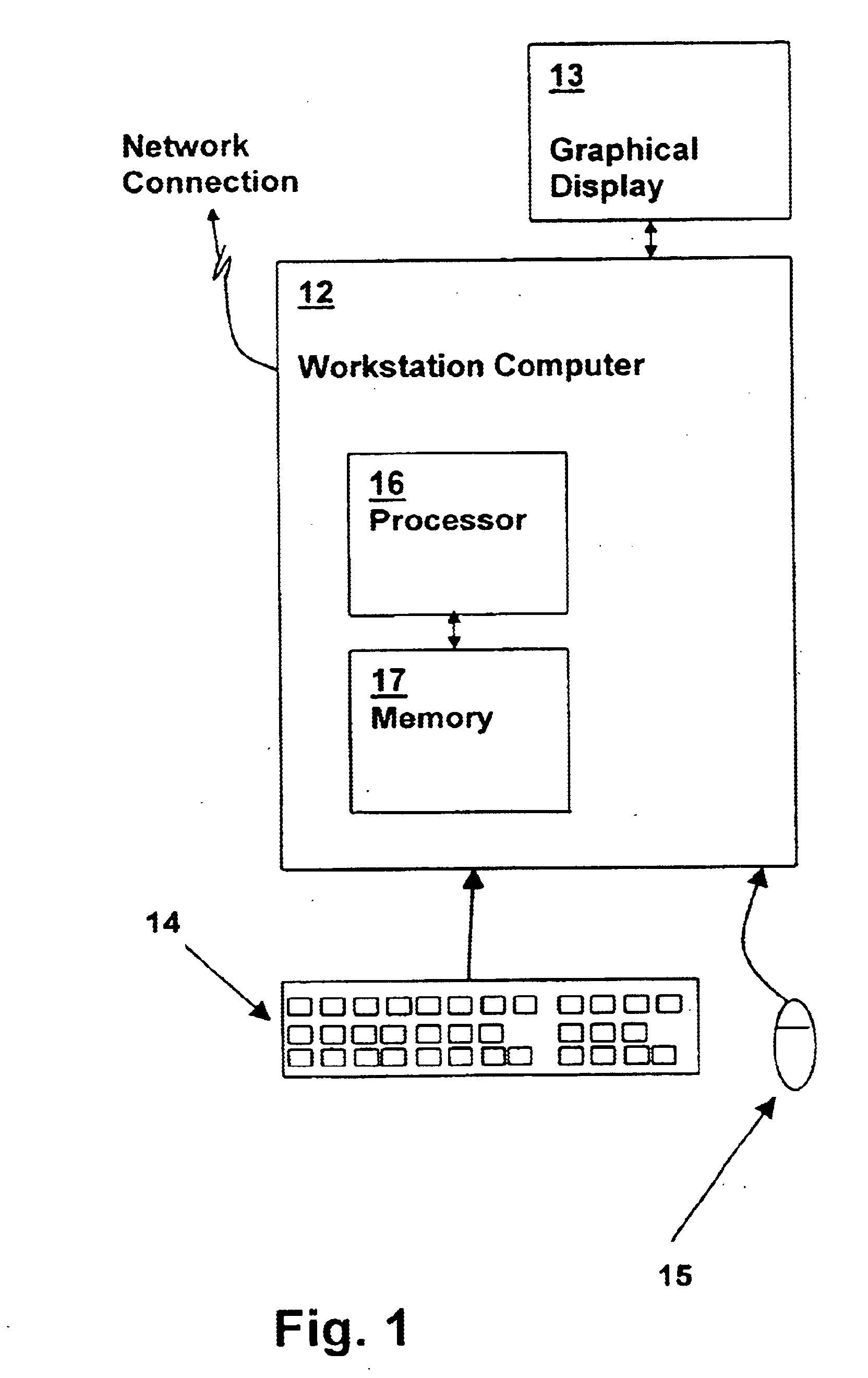
Referring to the figures, and particularly to FIG. 1, a workstation computer system, in which methods according to an embodiment of the present invention are performed, is depicted. A workstation computer 12, having a processor 16 coupled to a memory 17, for executing program instructions from memory 17, wherein the program instructions include program instructions for executing one or more methods in accordance with an embodiment of the present invention.

Workstation computer 12 is coupled to a graphical display 13 for displaying program output such as simulation results and circuit structure input and verification programs implementing embodiments of the present invention. Workstation computer 12 is further coupled to input devices such as a mouse 15 and a keyboard 14 for receiving user input. Workstation computer may be coupled to a public network such as the Internet, or may be a private network such as the various "intra-nets" and software containing program instructions embodyi...


PUM


Abstract

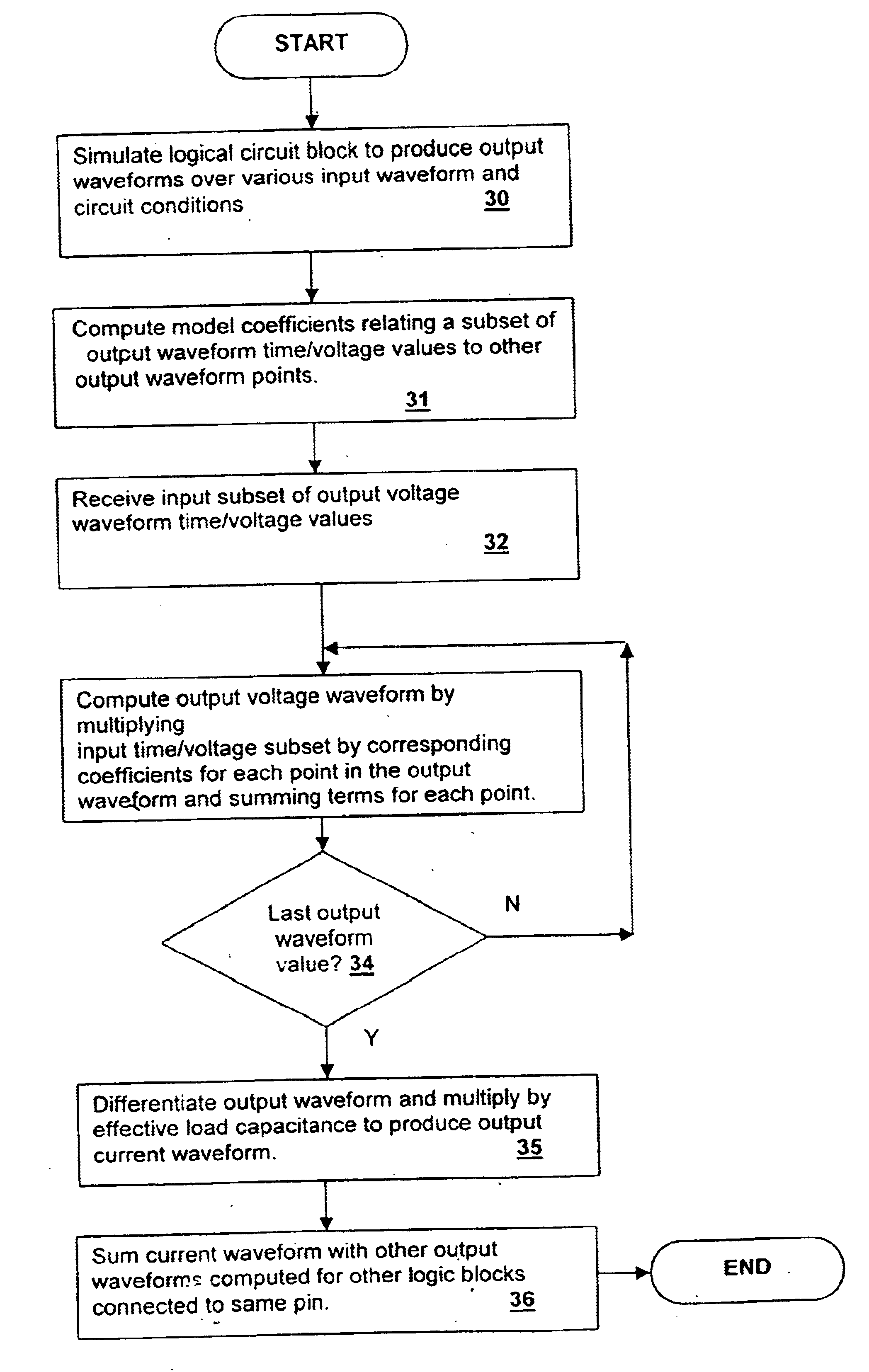
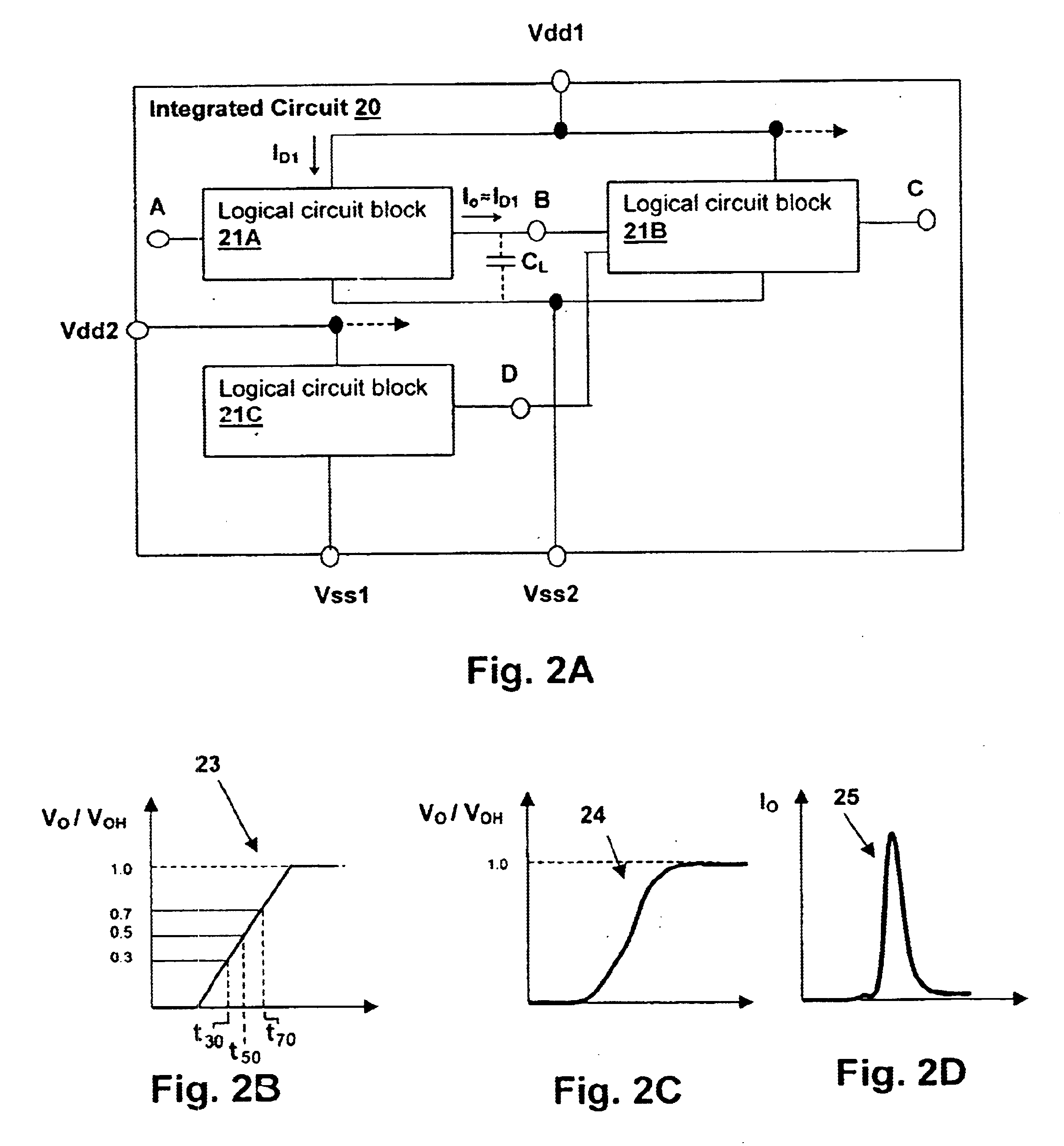
A method and system for power node current waveform modeling provides improved accuracy for logic gate and functional block power node current models in computer-based verification and design tools. An output voltage waveform is generated, with each point a linear function of a set of input values corresponding to times at which the output voltage reaches predetermined fractions of the supply voltage. A set of coefficients is used for each point, as each output voltage has a different linear dependency on the input values. The output voltage waveform model is differentiated and multiplied by an effective load capacitance to determine an output current waveform. The method and system retain compatibility with existing software by using input values already present in the digital simulation models (e.g., delay times) that yield a subset of output voltage points. The coefficients of the model are predetermined for a circuit from principle components analysis.

Description

1. Field of the InventionThe present invention generally relates to systems for modeling the behavior of integrated circuits such as verifiers, simulators and design tools, and more particularly to a computer program that includes modeling of digital integrated circuit power supply pin current waveforms.2. Description of Related ArtDesign tools and verification tools are necessary for modeling large-scale digital integrated circuits such as Very Large Scale Integration (VLSI) circuits. Millions of transistors and logic gates are often combined on a single die and the performance of the die is modeled using software that models the performance of the overall die based on known (modeled) performance of individual gates, inverter / buffer models of gates, or models of larger functional blocks.Power supply current for individual gates or blocks combines to generate the power requirements for the overall die, and will typically combine in sub-groups to several power and ground pins that ar...

Claims


Application Information

Patent Timeline
Patent Type & Authority Patents(United States)
IPC IPC(8): G06F17/50
CPCG06F17/5036G06F2217/78G06F2119/06G06F30/367
Inventor ACAR, EMRAHNASSIF, SANI RICHARD
Owner GLOBALFOUNDRIES U S INC
Learn More