Four-stroke engine with an oil spray generating assembly for lubrication

a technology of generating assembly and oil spray, which is applied in the direction of auxilary lubrication, lubricant level maintenance, lubrication elements, etc., can solve the problems of engine breakdown, water vapor rusting or oxidizing the engine, and friction created during the operation of the piston and the cranksha

Inactive Publication Date: 2004-08-03
ECI ENGINE
View PDF12 Cites 24 Cited by
  • Summary
  • Abstract
  • Description
  • Claims
  • Application Information

AI Technical Summary

Problems solved by technology

However, friction is created during the operation of the piston and the crankshaft.
The friction generates heat that will cause the engine to breakdown unless the friction and resultant heat are l

Method used


Image

  • Four-stroke engine with an oil spray generating assembly for lubrication
  • Four-stroke engine with an oil spray generating assembly for lubrication
  • Four-stroke engine with an oil spray generating assembly for lubrication

Examples


Embodiment Construction

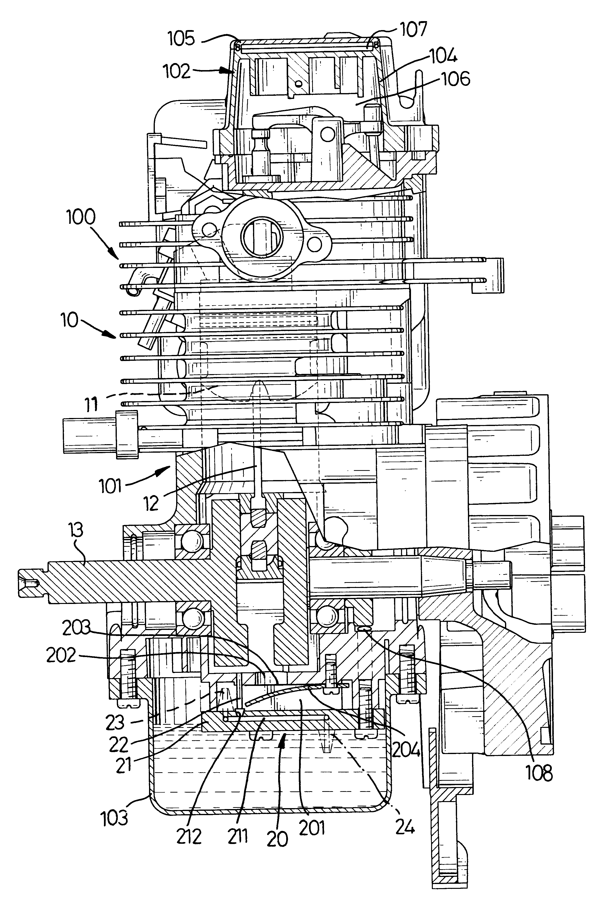
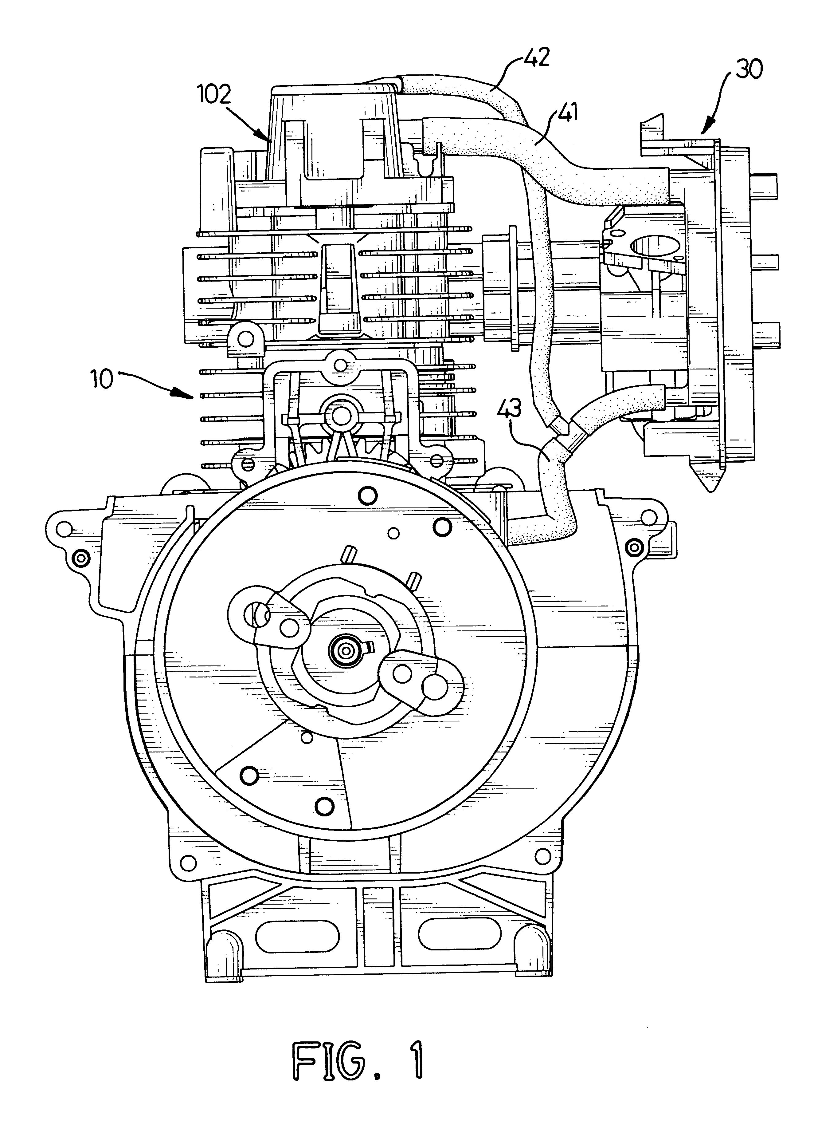
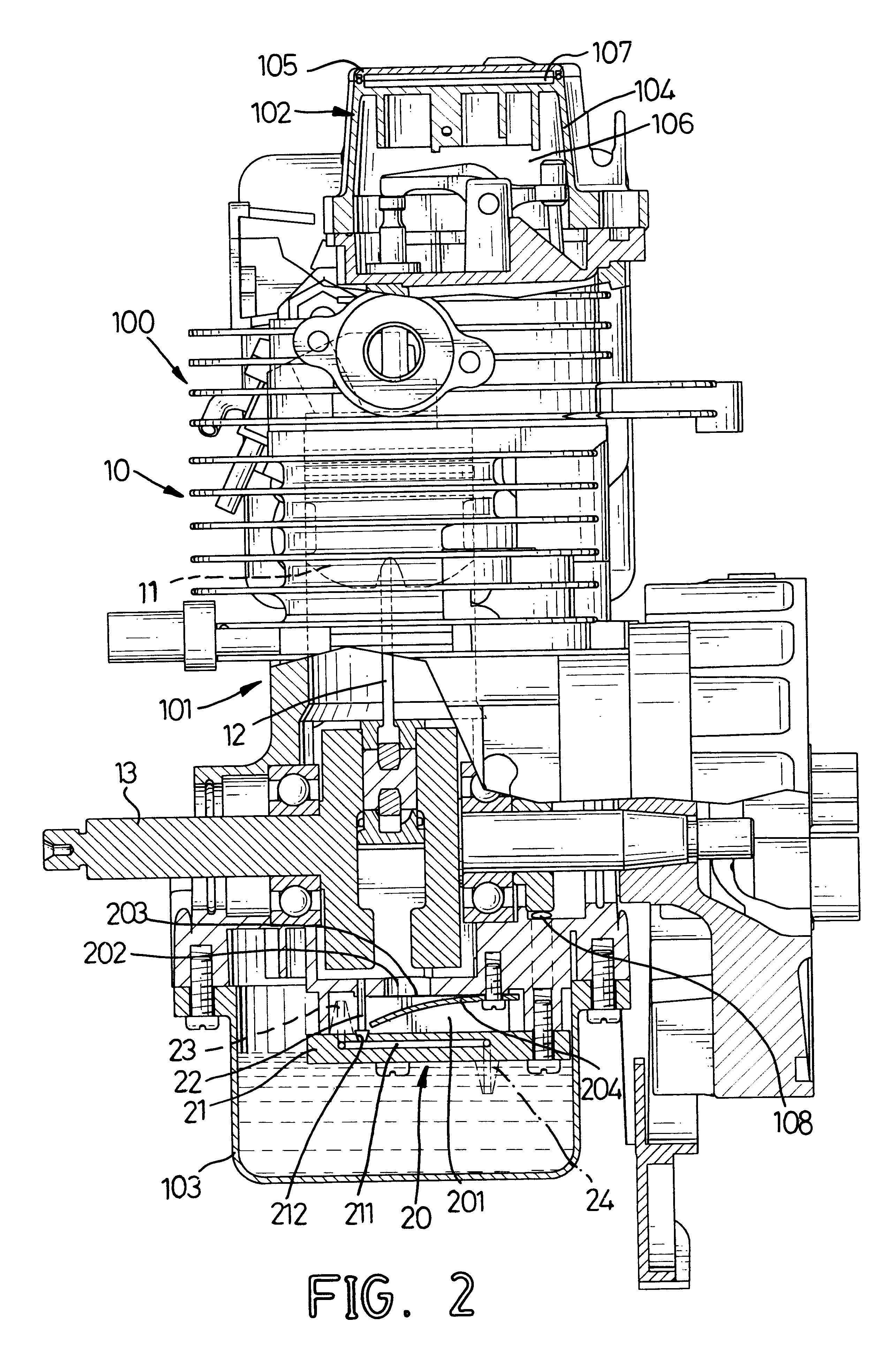
With reference to FIGS. 1 and 2, an internal combustion four-stroke engine in accordance with the present invention comprises an engine body (10), an oil spray generating assembly (20), an oil recycling assembly (30) and multiple connecting ducts (not numbered).

The engine body (10) has a block (100), a crankcase (101), a head (102) and an oil pan (103). The block (100) has a top (not numbered), a bottom (not numbered), a cylinder (not numbered), a piston (11) and a cylinder oil channel (not shown). The cylinder is formed in the block (100). The piston (11) is reciprocally mounted in the cylinder. The piston (11) will reciprocally move in the cylinder between two positions, called top-dead-center (TDC) and bottom-dead-center (BDC). One complete cycle of the piston (11) consists of a downward power stroke, an upward exhaust stroke, a downward intake stroke and an upward compression stroke. The cylinder oil channel is defined in the block (101) through the bottom and communicates with ...


PUM


Abstract

A four-stroke internal combustion engine includes a crankcase with a bottom, an oil pan and an oil spray generating assembly. The oil spray generating assembly having a closed sidewall, a valve, a bottom cap and nozzles is attached to the bottom of the crankcase and is enclosed by the oil pan. The closed sidewall is formed at the bottom of the crankcase to define a mist chamber enclosed by the bottom cap. The valve is mounted in the mist chamber with a valve port defined through the crankcase and a resilient valve flap corresponding to the valve port attached to the bottom of the crankcase. The nozzles are respectively mounted in the bottom cap out of the mist chamber inside the closed sidewall. The operation of the engine will produce an oil vapor for lubrication with the lubricating oil flowing out of the nozzles.

Description

1. Field of the InventionThe present invention relates to a four-stroke engine, and more particularly to a four-stroke internal combustion engine with an oil spray generating assembly to produce oil spray for lubrication.2. Description of Related ArtFour-stroke internal combustion engines were developed over one hundred years ago, to power machines that do a specific job and comprise a block, a cylinder, a piston, a crankcase and a cylinder head. The cylinder is formed in the block. The piston is movably mounted and moves reciprocally in the cylinder and has a piston head and a connecting rod. The connecting rod has a top end and a bottom end, and the top end is pivotally connected to the piston head. The crankcase is attached to the block and includes a bottom, a crankshaft and an oil pan. The crankshaft is rotatably mounted in the crankcase, and the bottom end of the connecting rod is attached rotatably to the crankshaft. Therefore, the reciprocating motion of the piston in the cy...

Claims


Application Information

Patent Timeline
IPC IPC(8): F01M9/00F01M9/10F01M1/08F01M11/00F01M11/06F01M1/00F01M1/04F02B63/02F02B63/00F16N7/32F16N7/00F02B75/02
CPCF01M1/04F01M1/08F01M9/10F01M11/064F02B63/02F16N7/32F02B2075/027
Inventor LEE, ANDYTENG, SHAW-LIUNG
Owner ECI ENGINE
Why Eureka
Try Eureka