Exhaust-valve lifting and lowering cam, turbocharged four stroke engine and valve timing control method

a four-stroke, turbocharged technology, applied in the direction of valve drives, electric control, machines/engines, etc., can solve the problems of valve interference with (comes in contact with) the piston, the valve is difficult to perform the general exhaust gas re-circulation (egr) of a large capacity, and the back-flow effect of the exhaust gas is substantially limited

a four-stroke, turbocharged technology, applied in the direction of valve drives, electric control, machines/engines, etc., can solve the problems of valve interference with (comes in contact with) the piston, the valve is difficult to perform the general exhaust gas re-circulation (egr) of a large capacity, and the back-flow effect of the exhaust gas is substantially limited

US20120042649A1Inactive Publication Date: 2012-02-23MITSUBISHI HEAVY IND LTD

Image

  • Exhaust-valve lifting and lowering cam, turbocharged four stroke engine and valve timing control method
  • Exhaust-valve lifting and lowering cam, turbocharged four stroke engine and valve timing control method
  • Exhaust-valve lifting and lowering cam, turbocharged four stroke engine and valve timing control method

Examples


Embodiment Construction

[0092]Hereafter, the present invention will be described in detail with reference to the embodiments shown in the figures. However, the dimensions, materials, shape, the relative placement and so on of a component described in these embodiments shall not be construed as limiting the scope of the invention thereto, unless especially specific mention is made.

[0093]Further, the present invention will be described in detail with reference to the modes (variations) shown in the figures. However, the dimensions, materials, shape, the relative placement and so on of a component described in these modes shall not be construed as limiting the scope of the invention thereto, unless especially specific mention is made.

[0094](First Mode)

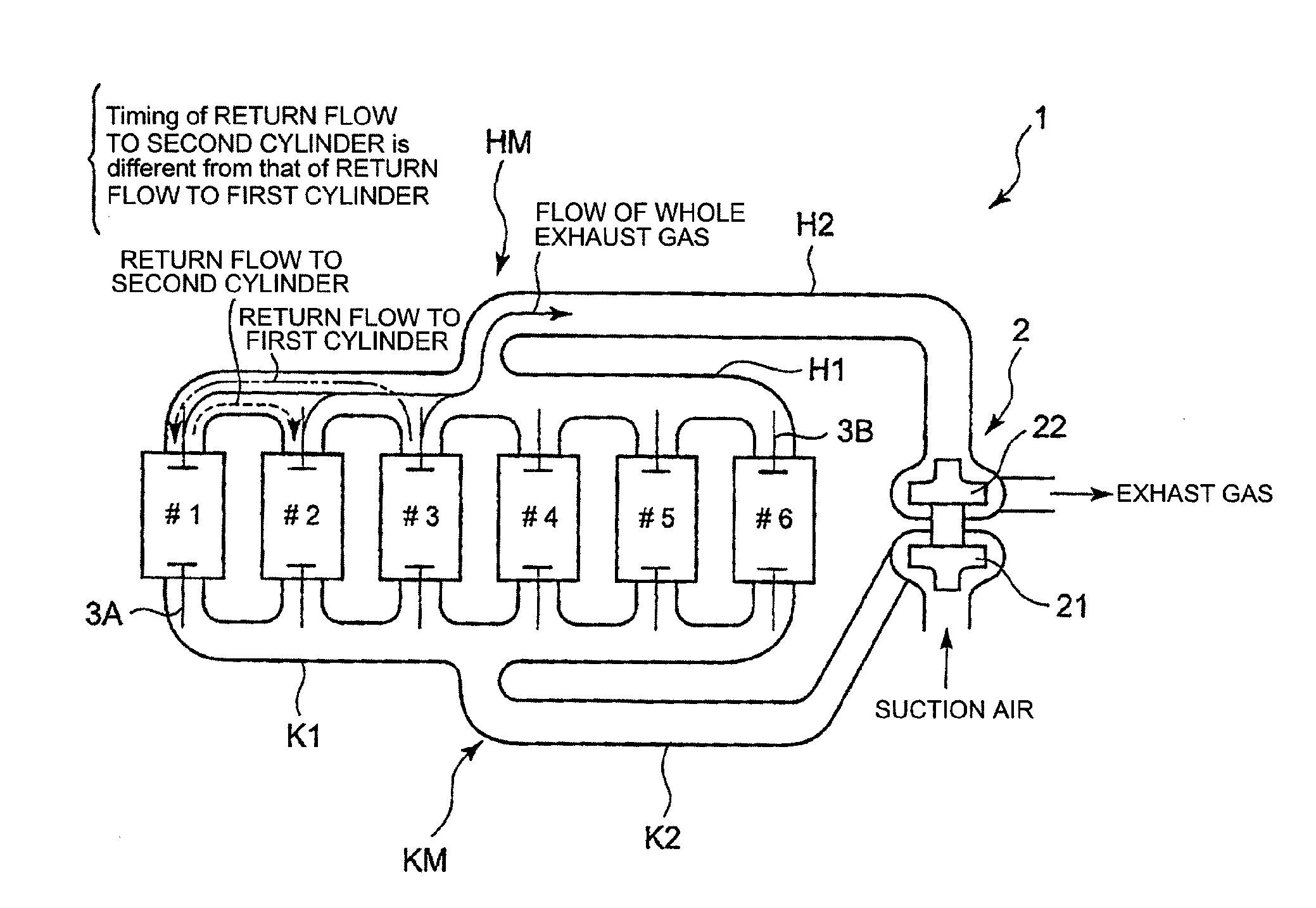
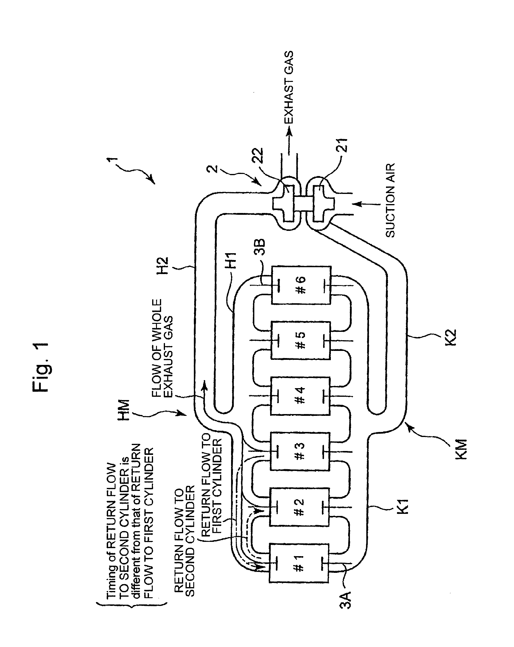
[0095]FIG. 1 shows an outline of a four-stroke cycle engine provided with a turbocharger according to the present invention. It is assumed that the turbocharged four-stroke cycle engine according to this mode (variation) is a diesel engine. The charge air side o...


PUM


Abstract

Providing a cam for lifting and lowering the exhaust valve so that the exhaust gas return-flow from one cylinder to another cylinder can be realized as greatly as possible, wherein the pistons and the exhaust valves do not come in contact with each other, and the valve control method does not depend on an electronic control approach. An exhaust cam for lifting and lowering the valve lift of the exhaust valve of one of the cylinders wherein the cam profile of the exhaust cam regarding the one of the cylinders including, but not limited to: a main exhaust lobe part for opening the exhaust valve so that the exhaust gas is discharged out of the cylinder; and, a gas return lobe part for opening the exhaust valve so that the quantity of the exhaust gas from the one of cylinders to the other cylinder is increased, the gas return lobe part being formed on the cam-follower descending part of the profile so as to delay the closing timing of the exhaust valve or maintain the valve lift-displacement regarding the exhaust valve larger, and wherein the cam profile is formed so that the interference between the exhaust valve and the piston is evaded and the overlap regarding the exhaust valve of the one cylinder and the exhaust valve of the other cylinder is increased by the manner that the main exhaust lobe part and the gas return lobe part rise outward from the base circle.

Description

BACKGROUND OF THE INVENTION[0001]1. Field of the Invention[0002]The present invention relates to an exhaust-valve lifting and lowering cam for an exhaust gas return-flow device which returns the exhaust gas to reduce NOx; a turbocharged four-stroke cycle engine; and a valve timing control method. The present invention especially relates to a large-scale four-stroke cycle diesel engine which is used for a land generator or a ship.[0003]2. Background of the Invention[0004]Conventionally, it is widely known that the concentration of nitrogen oxide (NOx) generated in the exhaust gas is reduced due to the reduction of the oxygen concentration and the increase of the specific-heat ratio when a part of the exhaust gas is returned to the inside of the engine cylinders. From environmental points of view, since NOx may cause photochemical smog, it is preferable to restrain the NOx generation. For this reason, it is performed to modify the opening or closing timings regarding the intake valves...

Claims


Application Information

Patent Timeline
23 Feb 2012
Publication
US20120042649A1
IPC
F02G3/00; F01L1/34; F02M25/07
CPC
F01L1/08; F02B37/00; F02D13/0246; F02D13/0261; Y02T10/18; F02M25/0748; F02M25/0752; Y02T10/47
Inventors
KANEKO, TAKASHI; TUJISHITA, HIROTO