Confocal holographic optical storage with non-overlapping records

a confocal holographic optical storage and record technology, applied in the field of three-dimensional technique of hologram recording, can solve the problems of difficult selective erasure of single holograms, diffraction efficiency of individual holograms to rapidly decline, and relatively complex methods of multiplexing

Inactive Publication Date: 2004-08-24
INSTITUT JOZEF STEFAN
View PDF1 Cites 5 Cited by
  • Summary
  • Abstract
  • Description
  • Claims
  • Application Information

AI Technical Summary

Benefits of technology

According to the invention, the volume of the hologram is reduced to the very limit allowing still the hologram to be reconstructed with sufficient reliability. The advantages of this method of recording are that the diffraction efficiency of single holograms is improved, the attained data density approaches the theoretical limit, and the optical system is simpler. By the present invention, furthermore, selective erasing of single holograms is attained, while unwanted erasure of holograms during readout is substantially reduced. The material into which data is written is shaped as a plate, and between single writes / reads of the holograms we merely shift the relative positions of the optical system and the plate for such a distance in the plane of the plate that the two consecutive holograms do not overlap. This writing technique is compatible with the known techniques of writing to and reading from rotating disk-shaped materials, which is why its implementation is cheaper and more reliable.
To record a hologram, a reference light beam is used, incident upon the storage material either from the same direction as the signal beam, or from the opposite direction. According to the present invention and in contradistinction to prior-art solutions, in the most favorable case the reference light beam used for recording illuminates the smallest possible volume of the storage material. The great amount of written data per single hologram is achieved on account of the fast lateral modulation of the signal beam, because of which the diameter of the signal beam inside the plate is substantially larger than that of the reference beam. The hologram is only written in the portion where the signal and the reference beams overlap, so its volume is equal to the volume illuminated by the reference beam. Consecutive holograms of data are written in adjacent portions of the plate in such a way that they do not overlap. The light stream density of the reference beam is substantially greater than that of the signal beam, so while a particular hologram is being written, erasure of adjacent holograms is almost negligible. The hologram is read back by means of a reference beam identical to the one that was used for writing. To be sure, in the readout process the refracted signal beam does propagate through the portions of the plate that contain other holograms, but owing to the small light stream of the refracted beam the erasing of adjacent holograms is negligible.

Problems solved by technology

The methods of multiplexing are relatively complex and, moreover, the writing of multiple holograms in the same space causes the diffraction efficiency of individual holograms to decline rapidly.
A further disadvantage with multiplexed holograms is that selective erasing of single holograms is difficult.
Although selective erasing is possible, it poses such high requirements upon the mechanical stability of the storage system as a whole that it is extremely uneconomical.
As a consequence of all the described problems related to multiplexing, all known methods of holographic data storage are still greatly limited in their use and still very far from reaching the theoretically predicted storage densities.
If the so-called photo refractive crystals are used as the storage material, a further serious drawback of the optical holographic storage emerges.
The problem consists in the unwanted erasure of the holograms while they are being read out, which affects multiplexed holograms even more severely because of the low diffraction efficiency of single holograms.
In the U.S. Pat. No. 6,040,930 a method of minimizing the volume of the hologram is disclosed by the authors, the results being, however, still far from what is theoretically possible.
If we were to combine optical holographic storage with any method of multiplexing which writes several additional holograms or parts thereof into the same volume, the situation would only get worse.

Method used


Image

  • Confocal holographic optical storage with non-overlapping records
  • Confocal holographic optical storage with non-overlapping records
  • Confocal holographic optical storage with non-overlapping records

Examples


embodiment 1

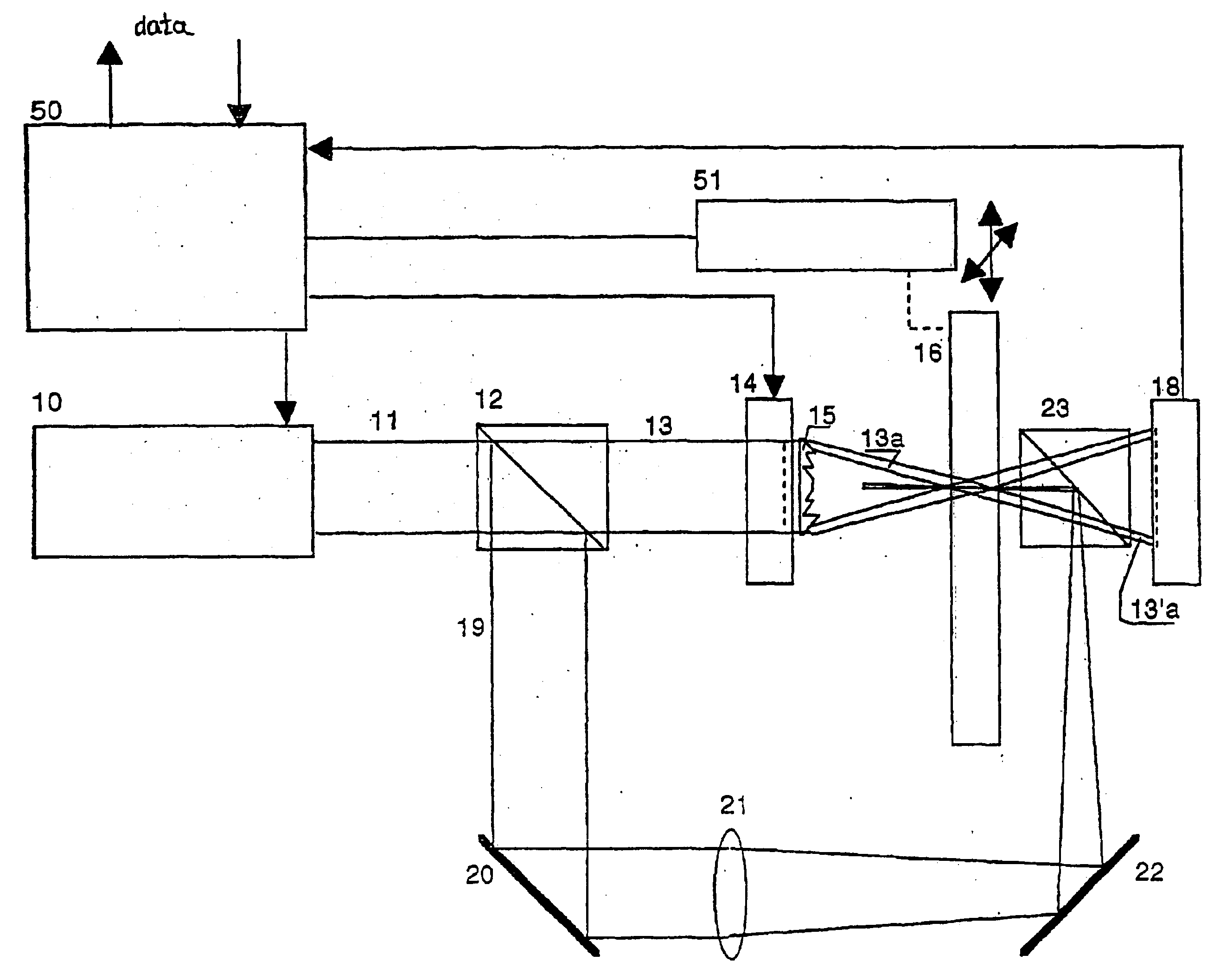
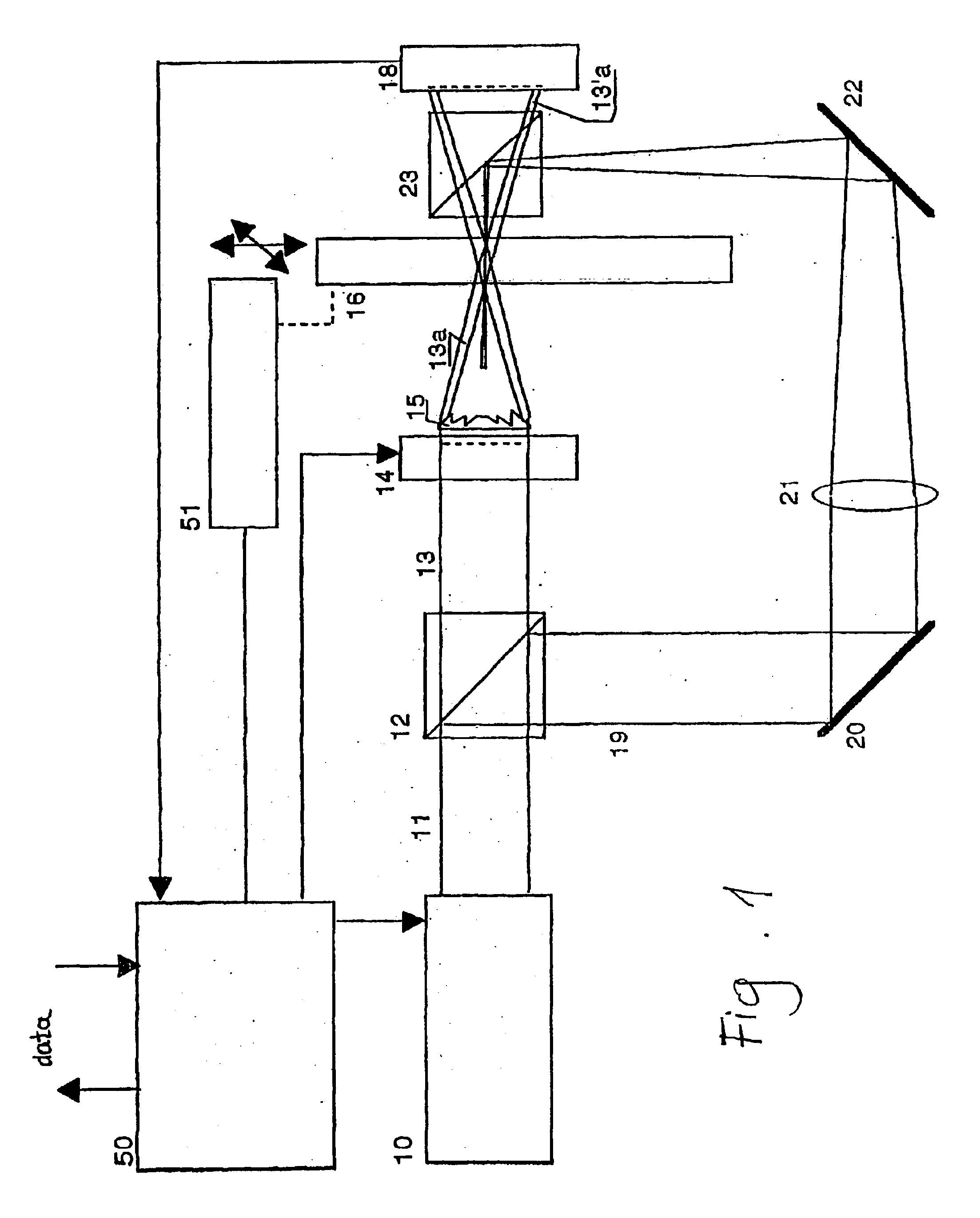
FIG. 1 is a schematic diagram of the system for holographic optical data storage and retrieval in a plate-shaped material 16. To write and read holograms, a laser 10 of a suitable wavelength and with a quality output beam 11 is required. The beam is split into a signal beam 13 and a reference beam 19 by a splitter 12. The signal beam travels through a modulator 14, which, being equipped with pixels with individually controllable permeability, amplitude-modulates the cross-section of the beam 13, thereby loading it with data. The lens 15, which may be a common lens, a Fresnel lens, or an array of microlenses, in close contact with the modulator 14, focuses the signal beam 13 into a beam, whose smallest cross-section lies in the median of the plate 16. In FIG. 1, a portion of the signal beam 13 is designated with the numeral 13a. The reference beam 19 is reflected from the mirror 20 and focused by the lens 21 of a suitable focal length. After being reflected from the mirror 22 and the...

second embodiment

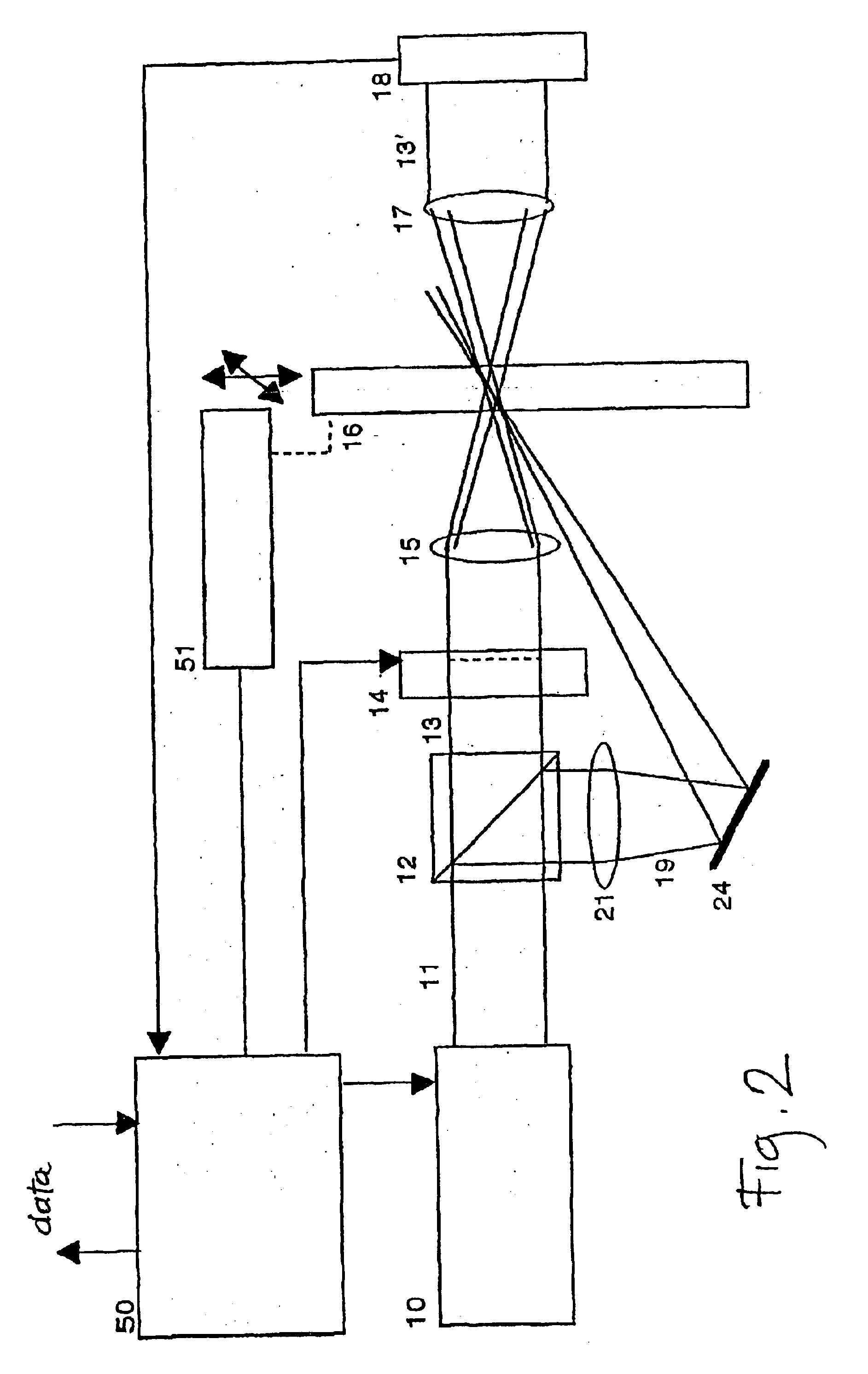
FIG. 2 is a schematic diagram of the system for holographic optical data storage and retrieval, which is a variation of the system in FIG. 1, differing therefrom in that the reference beam 19 impinges upon the storage plate 16 from the same direction as the signal beam 13. As in the previous case, it is required that the waist of the reference beam 19 lie in the median of the plate 16, which is achieved by appropriately selecting the distance from the lens 21 to the mirror 24 and further to the plate 16. In this case, the reference beam 19 impinges upon the plate 16 at an angle of 20 to 45 degrees, which does not alter the conditions of hologram writing and reading in a substantial degree.

The embodiment in FIG. 2 shows another possible modification of the second embodiment with respect to the first embodiment. The light modulator 14 is followed by the lens 15', which focuses the signal beam 13 into a beam, whose smallest diameter lies in the median of the plate 16. In this case, the...


PUM

PropertyMeasurementUnit
refractive indexaaaaaaaaaa
thicknessaaaaaaaaaa
thicknessaaaaaaaaaa

Abstract

The present invention relates to a method and a system for the storage of data in the form of volume holograms which do not mutually overlap. The storage medium consists of a high-sensitive material in the form of a plate of thickness D, in which a single hologram is essentially shaped as a cylinder with the minimal possible cross-section. The signal light beam is modulated with data and directed onto the plate-shaped storage material by means of a lens or a conventional optical system, illuminating an area of the material which, for a given amount of data, is the smallest possible. To record a hologram, a reference light beam is used, incident upon the storage material either from the same direction as the signal beam, or opposite thereto. The hologram is only written in the portion where the signal and the reference beams overlap.

Description

The present invention relates to a storage method and system for storing mutually non-overlapping volume holograms and to a confocal holographic optical data storage system with non-overlapping records. The invention pertains to the technical field of holographic optical data storage systems with high density storage capabilities. In the present patent application, a new method and system for storing data in the form of mutually non-overlapping three-dimensional holograms are disclosed.The invention provides a solution to the technical problem of improving the manner in which data is stored in the holographic optical storage medium.Optical storage is largely used today, e.g. in the form of music and data CDs, DVD discs and magneto-optical systems. All these systems are two-dimensional (2-D), which means they only store data in one plane or two at the most, the said two planes being both accessible from one side of the storage medium. The storage density is limited, by the nature of ...

Claims


Application Information

Patent Timeline
Patent Type & Authority Patents(United States)
IPC IPC(8): G03H1/04G11C13/04G11B7/00
CPCG03H1/0248G11C13/042G03H1/16G03H1/30G03H2001/0415G03H2222/42G03H2222/54
Inventor ZGONIK, MARKO
Owner INSTITUT JOZEF STEFAN
Why Eureka
Try Eureka