
Multiple trip point fuse latch device and method

Inactive Publication Date: 2005-04-19
III HLDG 12 LLC
View PDF15 Cites 14 Cited by
  • Summary
  • Abstract
  • Description
  • Claims
  • Application Information

AI Technical Summary

Benefits of technology

[0008]These and other problems are generally solved or circumvented, and technical advantages are generally achieved, by preferred embodiments of the present invention that comprise multiple trip points for a fuse latch. This may be accomplished, for example, by providing multiple read inputs to a fuse latch that enable the altering of the resistive trip point of the fuse latch. Changing the trip point permits the use of a test procedure that may analyze the margins of a fuse latch during the fuse read operation. The results of the test procedure then may be used to identify whether fuse latches on a semiconductor device possess sufficient reliability. If not, the semiconductor device may be redesigned, replaced, repaired or discarded, for example. Preferred embodiments of the present invention may include flip-flops comprising fuse latches connected in series to form shift registers. Such a configuration may be used to efficiently read out fuse values for integrated circuit analysis.
[0013]An advantage of a preferred embodiment of the present invention is that a fuse latch may be provided with multiple fuse latch trip points.
[0014]Another advantage of a preferred embodiment of the present invention is that multiple fuse latch trip points may provide reliability regarding the operating margins of a fuse latch.
[0015]Another advantage of a preferred embodiment of the present invention is that a reliability analysis of analog fuse resistance may be implemented in a digital manner by comparing binary data values during different precharge-read-shift cycles.
[0016]Yet another advantage of a preferred embodiment of the present invention is that the reliability of thousands of fuse latches may be evaluated by accessing a very small number of input and output signals.

Problems solved by technology

As a result, the fuse link is intentionally damaged and exhibits a higher resistance compared to its resistance before the fuse blow.
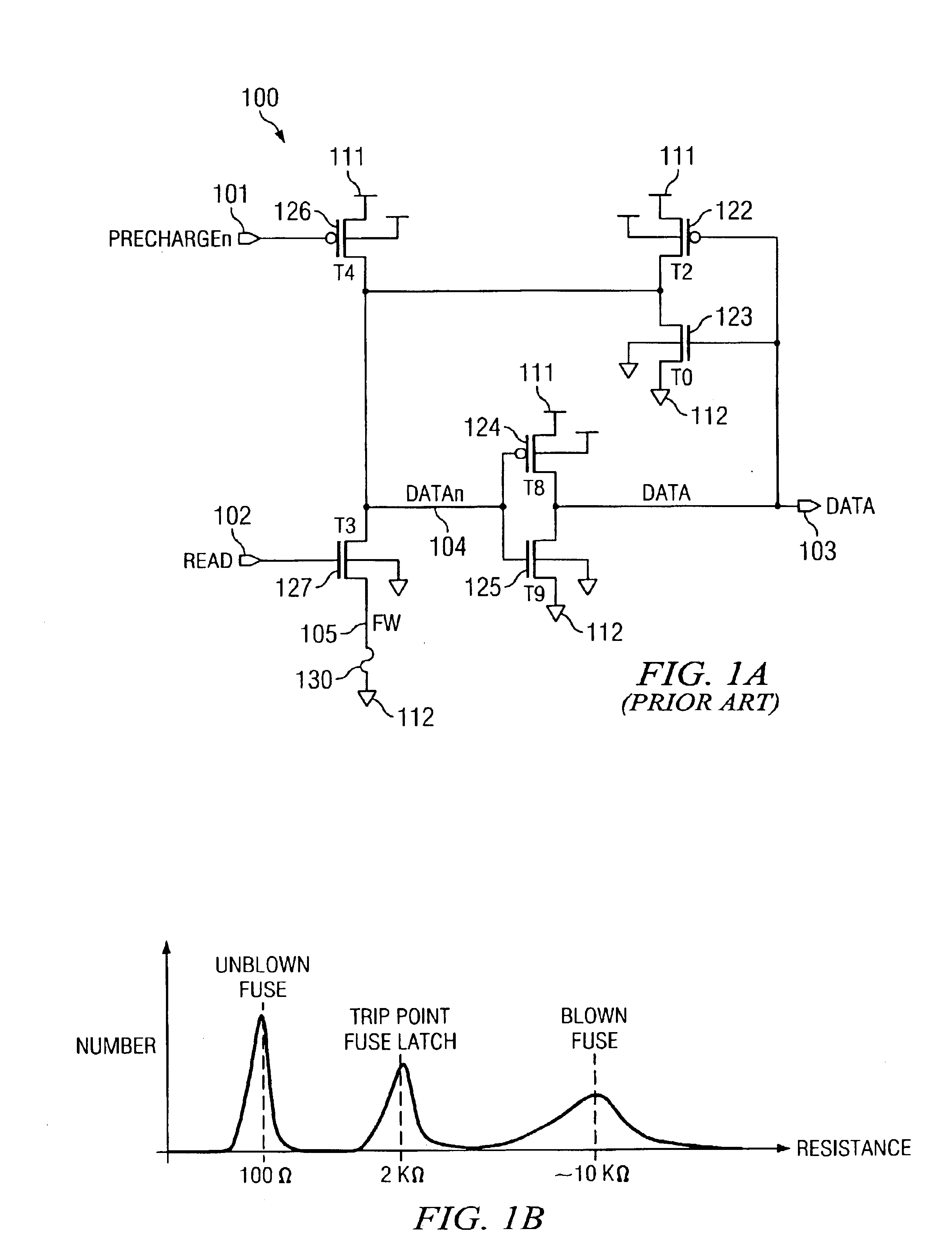
Therefore, a prior art fuse latch circuit generally cannot be properly tested for reliability of operation.

Method used


Image

  • Multiple trip point fuse latch device and method
  • Multiple trip point fuse latch device and method
  • Multiple trip point fuse latch device and method

Examples


first embodiment

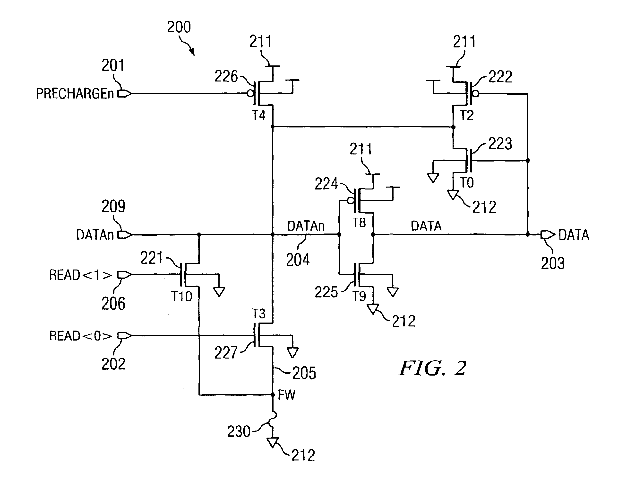
[0079]With reference now to FIG. 2, there is shown the present invention, which overcomes deficiencies of prior art fuse latch 100. In addition to comprising elements from fuse latch 100 of FIG. 1, fuse latch 200 comprises a second read switch, here implemented as NFET 221. This read switch is located in parallel to the first read switch (here implemented as NFET 227). NFET 221 is in the conducting state if input read signal 206 assumes a high state.

[0080]Accordingly, by having two read switches in parallel, three switch configurations can provide three different current paths for the read operation of the fuse latch. Specifically, input signal 206 may be high and input signal 202 may be low, input signal 206 may be low and input signal 202 may be high, and finally both input signals 206 and 202 may be high. If the resistances of the NFETs 221 and 227 are not identical in the conducting state, each of the three configurations exhibits a different resistance between node 204 and node...

second embodiment

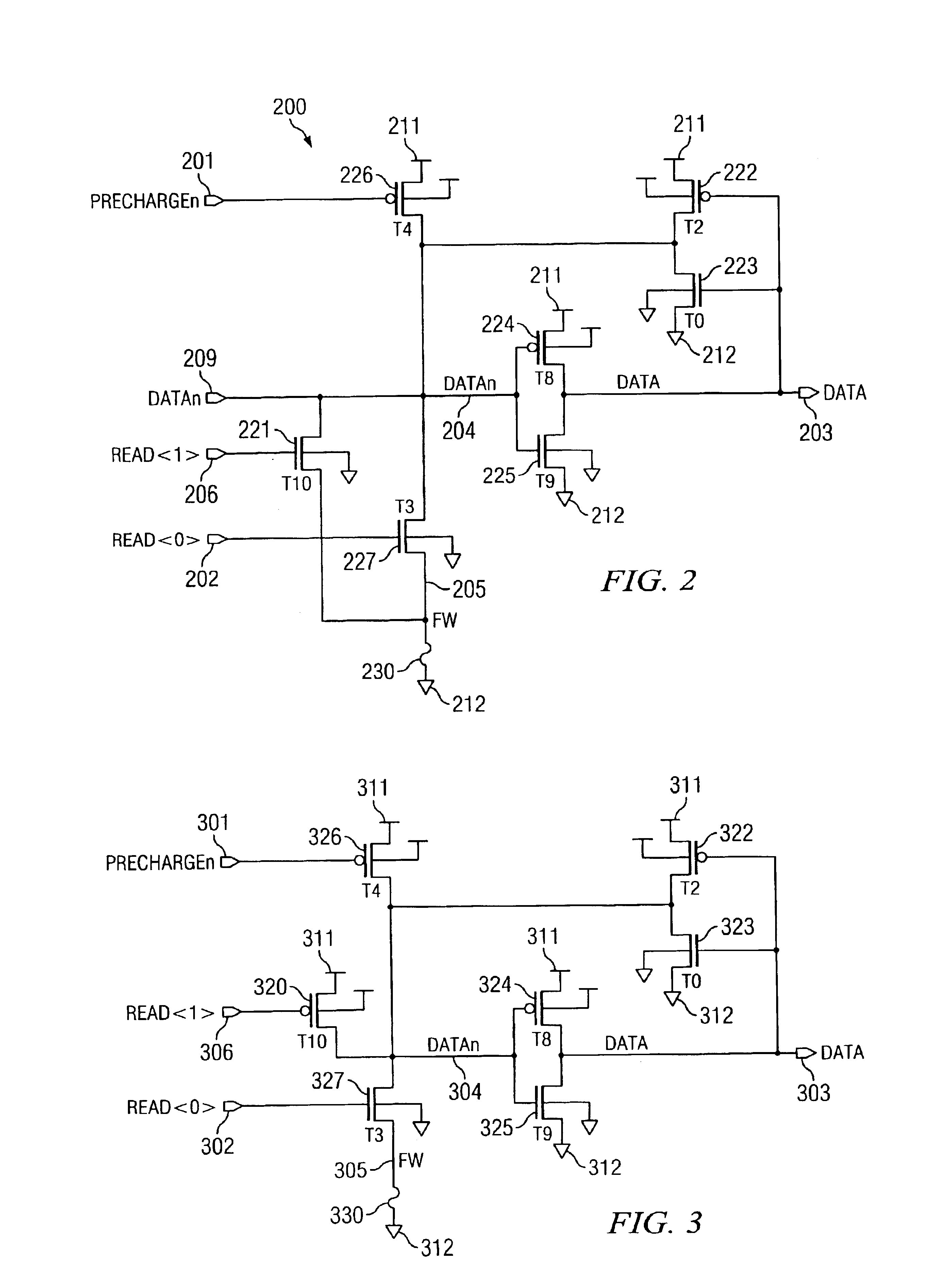
[0082]FIG. 3 shows the present invention. In this embodiment, an additional read switch is provided, here implemented as PFET 320. This read switch connects node 304 to positive power supply 311 during a read operation. Read switch 320 is controlled by read signal 306. In this embodiment, two different configurations provide different current paths for a read operation. When read signal 306 is set high, PFET 320 is not conducting, and the fuse latch operates similar to the prior art fuse latch of FIG. 1. If PFET 320 is turned on by bringing read signal 306 low during the read operation, however, two PFETs in parallel, namely 322 and 320, provide a current path from node 304 to positive power supply 311. Therefore, the trip point of the fuse latch will be lower, because the resistance of the fuse has to be lower to trip the latch from a high to a low state on node 304. Again, with the ability to change the trip point of the fuse latch by switching the read signal 306, a test procedur...


PUM


Abstract

A multiple trip point fuse latch device and method is disclosed. Multiple read inputs to a fuse latch enable the altering of the resistive trip point of the fuse latch. A multiple trip point fuse latch may be combined with a slave latch to form a master-slave flip-flop, and multiple master-slave flip-flops may be connected in series to form a shift register. Changing the trip point permits the use of a test procedure that may analyze the margins of a fuse latch during the fuse read operation.

Description

TECHNICAL FIELD[0001]Aspects of the present invention relate generally to a fuse latch device and method, and more particularly to a multiple trip point fuse latch device and method.BACKGROUND[0002]Semiconductor integrated circuits, such as processors, microcontrollers, memories, etc., incorporate fuse elements that allow individual configuration of each chip. Examples of parameters capable of being adjusted on a per chip basis are internal timings, supply voltage level, chip identification number, repair information, and the like. In particular, the latter may be used in memory circuits (e.g., DRAMs) to control the manner in which spare elements are used to replace defective elements. With the ever-growing memory capacity of these chips, the number of fuses has also increased. For example, a typical 64 MB DRAM circuit may contain a few thousand fuse elements.[0003]Commonly, a fuse is evaluated by a fuse latch circuit, which translates the analog resistance value of the fuse link in...

Claims


Application Information

Patent Timeline
IPC IPC(8): G11C17/14G11C29/08G11C29/04G11C29/02G11C17/16
CPCG11C17/16G11C29/08G11C29/027G11C29/02
Inventor LEHMANN, GUNTHERROBSON, NORMAN
Owner III HLDG 12 LLC
Learn More