Power line communications

a technology of power line communication and communication channel, applied in the field of power line communication, can solve the problems of unplanned rf energy radiation, radiation problems, and distribution network not designed to carry rf signals

Inactive Publication Date: 2004-08-31
RPX CLEARINGHOUSE
View PDF13 Cites 81 Cited by
  • Summary
  • Abstract
  • Description
  • Claims
  • Application Information

AI Technical Summary

Problems solved by technology

One of the problems with transporting RF signals over the electricity distribution network is that of unwanted radiation of RF energy.
The distribution network was not designed to carry RF signals.
The internal wiring at subscribers' premises S is unscreened, and could potentially cause radiation problems.
This is because screening is considered unnecessary at the 50 Hz mains frequency.
This is a undesirable as it causes interference with equipment operating at these frequencies.
This radiation may also violate regulations on Electromagnetic Compatibility (EMC).
However, the majority of substations are u

Method used


Image

  • Power line communications
  • Power line communications
  • Power line communications

Examples


Embodiment Construction

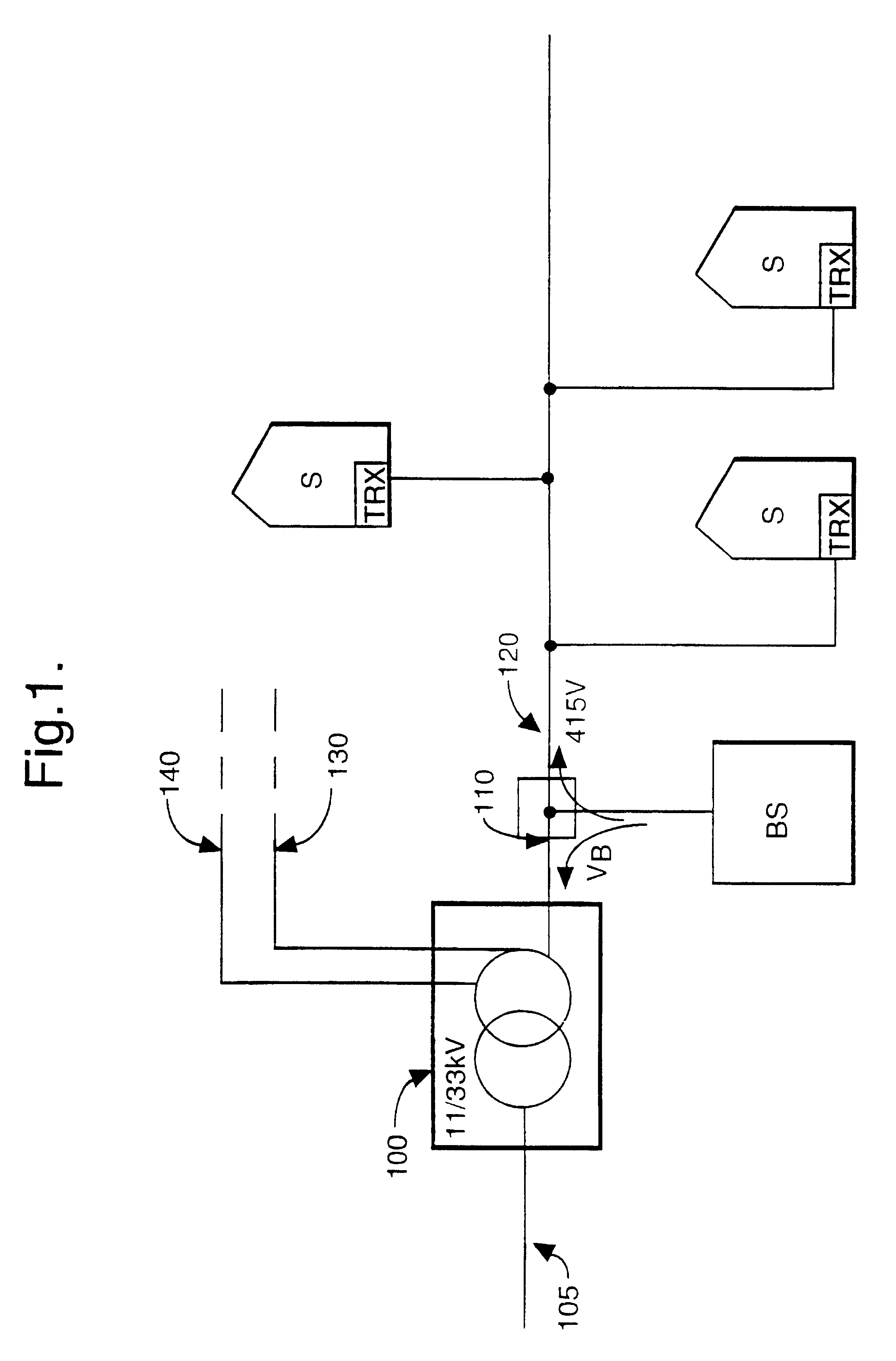
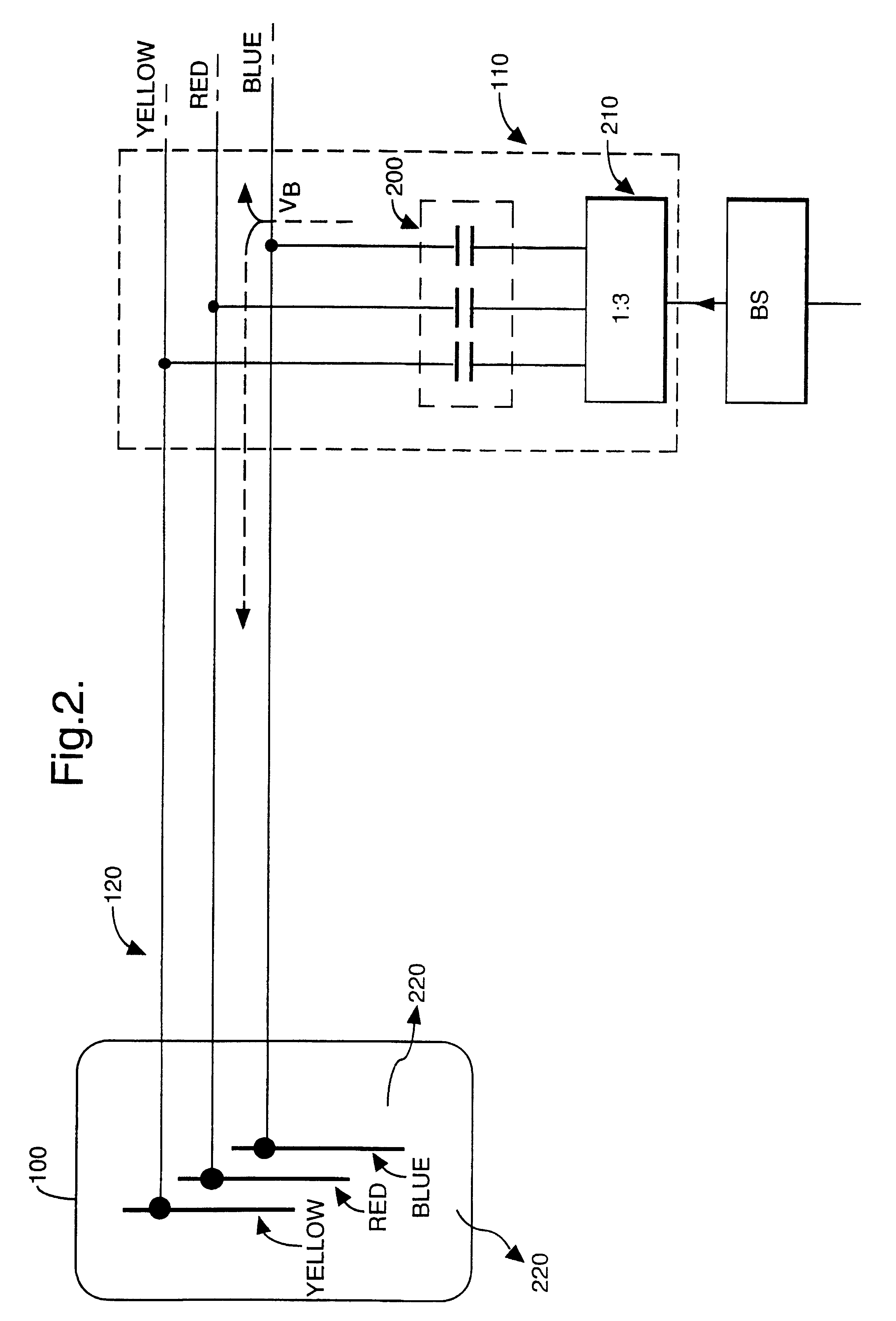
Referring again to FIG. 1, this shows an electricity distribution network which transports telecommunications signals. FIG. 2 shows part of this network in more detail. Distribution cable 120 has three separate phase lines: Blue, Red and Yellow. Each of the phase lines are coupled to a respective busbar in substation 100. The output of basestation BS is coupled to a three-way splitter 210. Each of the three output lines is coupled, via a high-pass filter unit 200 to a respective phase line of cable 120. The mains filter serves to pass only signals in the RF bands which are used for transmission of telecommunications signals and to block the flow of mains electricity into the basestation. Telecommunications signals propagate along cable 120 in two directions; towards substation 100 and towards subscribers. Signal V.sub.B is shown on the blue phase line. Telecommunications signals reaching substation 100 radiate RF energy 220.

FIG. 3 shows the same section of the network as that shown ...


PUM


Abstract

An apparatus for coupling signals to a transmission line, such as a power line (120). The apparatus comprises an input for receiving a wanted signal; a first coupler for coupling the wanted signal (Vmain) onto the line at a first position (Y); a cancelling means (WB, WR, WY), coupled to the input, for deriving a cancelling signal (Vaux) from the wanted signal; a second coupler for coupling the cancelling signal onto the line at a second position (X), spaced from the first position; wherein the wanted signal and the cancelling signal destructively combine in a single direction of propagation along the line while enabling the wanted signal to propagate in the other direction along the line. The apparatus can be used to minimise radiation from an unshielded part of an electricity distribution network, such as substation (100), or to allow re-use of a frequency band on other power lines.

Description

This invention relates to an apparatus and method for coupling signals onto a transmission line. It has particular application to coupling radio frequency (RF) signals onto an electricity distribution network which is used to transport telecommunications signals.BACKGROUND TO THE INVENTIONIt is known to transport telecommunications signals over an electricity distribution or power transmission network. Patent Application WO 94 / 09572 A1 (NORWEB) describes such a network. Delivering a telecommunications service in this manner is attractive as it overcomes one of the greatest costs in providing a new telecommunications network i.e. installing cabling to each subscriber. Existing electricity distribution cabling is used to carry the telecommunications signals.FIG. 1 shows an electricity distribution network which is adapted to carry telecommunications signals. Mains electricity enters the network from an 11 kV transmission line 105 and is transformed by substation 100 into a 415V supply...

Claims


Application Information

Patent Timeline
IPC IPC(8): H04B3/54H04B3/56
CPCH04B3/54H04B3/56H04B2203/5408H04B2203/5441H04B2203/5458H04B2203/5466H04B2203/5483H04B2203/5491
Inventor RICKARD, ROBIN PAUL
Owner RPX CLEARINGHOUSE
Why Eureka
Try Eureka