
Sorting grain during harvesting

a technology of grain and harvesting, applied in the field of sorting grain during harvesting, can solve the problems of inaccurate information, long time until the farmer gets a better quality of his grain, and difficulty in correctly determining the protein content of the produ

Inactive Publication Date: 2004-09-14
FOSS ANALYTICAL AB (SE)
View PDF12 Cites 19 Cited by
  • Summary
  • Abstract
  • Description
  • Claims
  • Application Information

AI Technical Summary

Benefits of technology

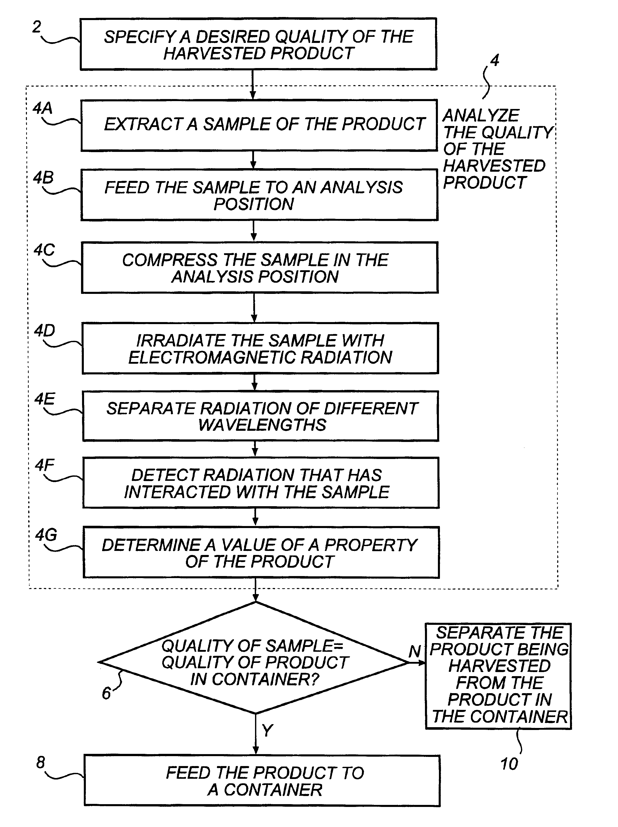
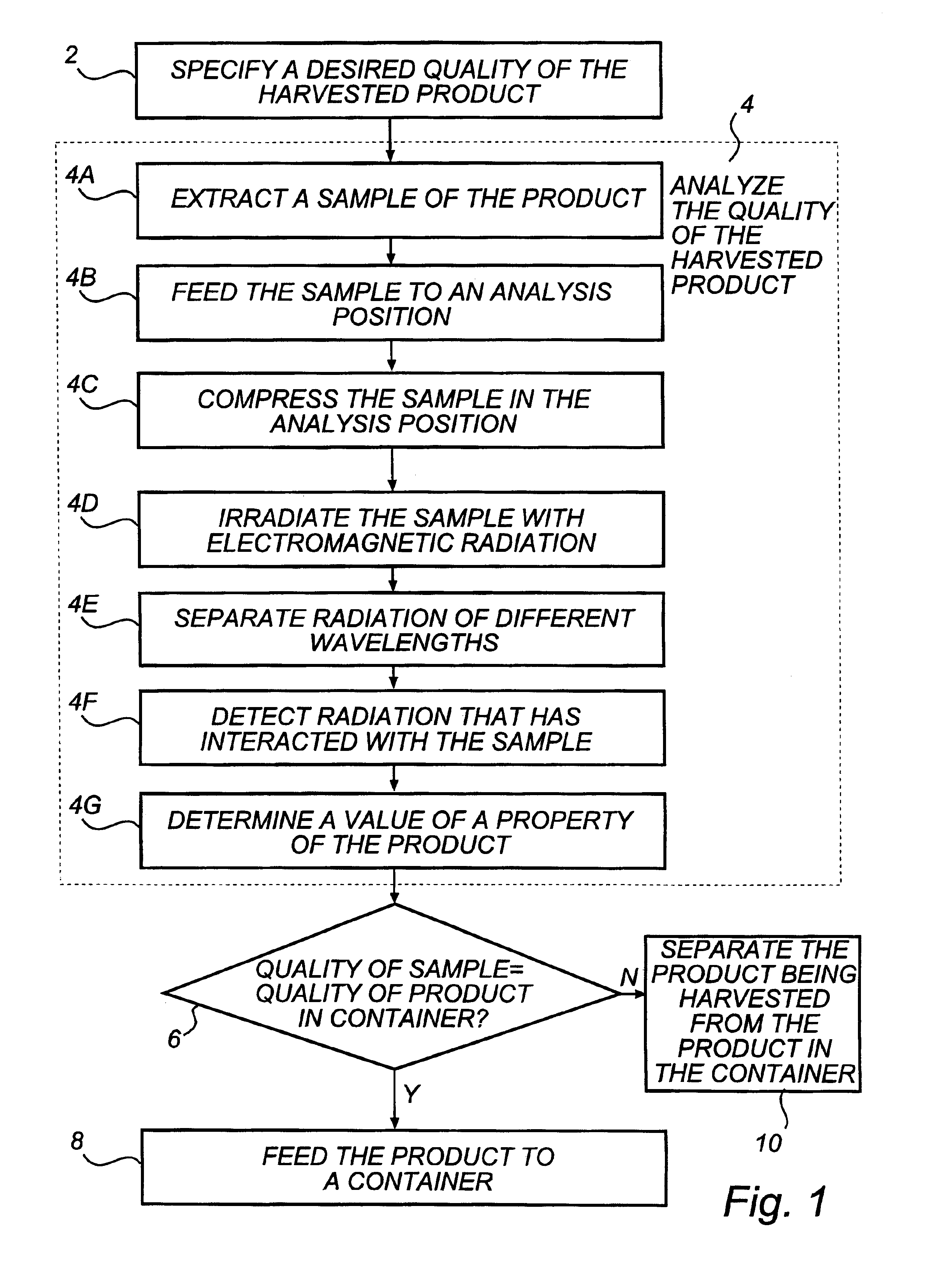
Thanks to the invention, a process operator can set a desired quality of the agricultural product. By analyzing the quality of the product as it is being processed, the method can ensure that different qualities of the product are not mixed. In this way, if a farmer has different qualities in different parts of his field, the different qualities will not be mixed during harvesting. When the product has been harvested from the field, the farmer could have two or more loads of products of different qualities. He will then be able to charge a high price for the product of fine quality, instead of charging a common, lower price for the product of both qualities.
According to another embodiment, the shaft is rotatingly moveable around a rotational axis that is parallel to the inlet and the outlet. This implies that it is easy to empty a sector. It might even be possible to include a cleaning device for pushing the sample out of the sector.

Problems solved by technology

However, it takes a long time until the farmer gets a better quality of his grain.
The measurements might then give an incorrect result of the determined amounts of the constituents in the sample.
In the case of e.g. barley or oats, the product is covered by a hull, which will lead to problems in correctly determining the protein content of the product, since the hull and the core of the particles are not equally composed.
Since the measurement is performed during processing of the product, such vibrations are frequently occurring.
As soon as the product that is being harvested is no longer of the same quality as the harvested product in the container, there is a risk of mixing two differing qualities of the product.
This also implies that the risk of pinholes decreases, i.e. holes through the sample, through which the radiation could pass unaffected from the radiation source to the detector.
This diminishes the risk of pinholes and movements in the sample during the analysis.
This means that the cavity does not have a uniform thickness in cross section.

Method used


Image

  • Sorting grain during harvesting
  • Sorting grain during harvesting
  • Sorting grain during harvesting

Examples


first embodiment

Referring to FIGS. 5-10, different embodiments of the sample holder 34 will be described. In FIG. 5, the sample holder 70 is shown. The outlet 72 can be closed by means of an outlet shutter 74. The outlet shutter 74 shuts the flow of products from the shaft 75. The inlet can be closed by means of an inlet shutter 76. The inlet shutter shuts the flow of products to the shaft 75. Thus, a product sample 77 can be fixated during measurement. The outlet shutter 74 is opened to remove a product sample 77 from the shaft 75. Then, the outlet shutter is closed and the inlet shutter 76 could be opened to feed a new sample 77 into the sample holder 70. The inlet shutter 76 could also be held closed for obtaining a reference spectrum on an empty shaft 75. The source head 78 is provided inside the shaft 75. A motor 79 controls how much the source head 78 is inserted into the shaft 75 for adjusting the sample thickness that is being measured upon. Alternatively, the source head 78 is fixed and on...

second embodiment

In FIGS. 6-7, the sample holder 80 is shown. In this embodiment, the shaft comprises a rotatable brush wheel 82. The wheel 82 rotates around a rotational axis that is perpendicular to the flow of products in the inlet 84 and the outlet 86. The brush wheel 82 comprises paddles 88 that extend radially from the rotational axis. Two adjacent paddles 88 form a sector 90, which is a cavity for holding the sample. The brush wheel 82 is divided into several sectors 90. The rotation of the brush wheel 82 is performed stepwise from a first position 92, where a sector 90 is filled by a product sample from the inlet 84, to a second position 94, where the sample is irradiated and analyzed, and further to a third position 96, where the sector 90 is emptied. When the brush wheel 82 is rotated, the sectors 90 are filled continuously for acquiring new samples for analysis. By turning the direction of rotation of the brush wheel 82, an empty sector 90 could be presented to the second position 94 and ...

third embodiment

However, in the sample holder 100, the brush wheel 102 is arranged to rotate around a rotational axis parallel to the direction of the flow of particles in the inlet 110 and the outlet 122. As a result, the sample holder 100 could comprise a cleaner (not shown) for effectively emptying the sectors 106 at the outlet 122. The cleaner could be realized as a piston, which is pushed through the sector 106 in the third position 114. This implies that the sectors 106 could be completely emptied, even for moist samples.


PUM

PropertyMeasurementUnit
wavelengthsaaaaaaaaaa
electromagnetic radiationaaaaaaaaaa
distanceaaaaaaaaaa

Abstract

A method for segregating qualities of an agricultural product during processing of the product comprises the step of setting a desired range of a measurement value (2). The measurement value represents a property of the product and defines a first quality of the product for which the measurement value is inside the range and a second quality of the product for which the measurement value is outside the range. The method further comprises the step of analyzing (4) the quality of the product that is being processed. The step of analyzing comprises the steps of continuously extracting samples of the product (4a), irradiating each sample by electromagnetic radiation (4d), spatially separating electromagnetic radiation of different wavelengths (4e), and detecting electromagnetic radiation emitted from the sample (4f). The step of detecting produces intensity signals indicative of detected electromagnetic radiation of different wavelengths. The step of analyzing further comprises the steps of determining a sample value of said property of the product from the intensity signals, and determining a measurement value (4g) from at least one sample value. The method further comprises the step of separating the product of said first quality from the product of said second quality on the combine.

Description

The present invention relates to a method for segregating qualities of an agricultural product during processing of the product. The invention also relates to a measuring instrument for analyzing the quality of an agricultural product. The measuring instrument is arranged on an implement for treatment of the product.TECHNICAL BACKGROUNDIn agricultural industry, it is today common knowledge that the price of an agricultural product is decided by the percentage of the constituents of the product. When a transaction is to be agreed upon, a sample of the product is analyzed to decide the quality.Today, several methods exist for deciding the constituents in an agricultural product. The product could be analyzed by wet-chemical methods or by spectroscopy. The latter is more easily performed and considerably faster and is therefore often preferred. A grain marketer, to whom the farmer sells his products, usually performs the analysis when the transaction is made and different loads of the ...

Claims


Application Information

Patent Timeline
Patent Type & Authority Patents(United States)
IPC IPC(8): G01N21/31G01N21/35G01N1/02
CPCA01D41/1271G01N21/359G01N21/3563G01N2001/021A01D41/1277
Inventor SJODIN, ROBERT
Owner FOSS ANALYTICAL AB (SE)
Learn More