Transmission coil module for wireless power transmitter

a technology of transmission coil and transmitter, which is applied in the direction of transformer/inductance coil/winding/connection, inductance, circuit arrangement, etc., can solve the problems of requiring time and effort from users, other electronic appliances or humans to charge batteries, and a new power supply to these appliances or sensors, etc., to achieve the effect of desired quality

Active Publication Date: 2019-09-19
LG INNOTEK CO LTD
View PDF0 Cites 0 Cited by
  • Summary
  • Abstract
  • Description
  • Claims
  • Application Information

AI Technical Summary

Benefits of technology

[0014]In addition, embodiments provide a transmission coil module for a wireless power transmitter, which may maintain a desired quality as the result of mounting transmission coils in the wireless power transmitter in a modular device.

Problems solved by technology

Thus, problems related to the supply of power to these appliances or sensors have newly arisen.
In addition, as the kinds of portable appliances, such as, for example, mobile phones, Bluetooth handsets, and music players such as iPod, have rapidly increased, the task of charging a battery demands time and effort on the part of the user.
The electromagnetic resonance method is hardly influenced by an electromagnetic wave, and therefore is harmless to other electronic appliances or humans.
In contrast, the electromagnetic resonance method may be used at a limited distance and in a limited space, and the energy transfer efficiency thereof is somewhat low.
However, when the arrangement and fixing of the coils and the electrical connection with peripheral circuits are changed due to various factors in the process of manufacturing the wireless power transmitter, wireless power transmission having a desired quality may not be realized.

Method used


Image

  • Transmission coil module for wireless power transmitter
  • Transmission coil module for wireless power transmitter
  • Transmission coil module for wireless power transmitter

Examples


Embodiment Construction

[0033]Hereinafter, an apparatus and various methods, to which the embodiments are applied, will be described in more detail with reference to the accompanying drawings. The suffixes “module” and “unit” of elements herein are used for convenience of description and thus can be used interchangeably and do not have any distinguishable meanings or functions.

[0034]In the following description of the embodiments, it will be understood that, when each element is referred to as being formed “on” or “under” the other element, it can be directly “on” or “under” the other element or be indirectly formed with one or more intervening elements therebetween. In addition, it will also be understood that “on” or “under” the element may mean an upward direction and a downward direction of the element.

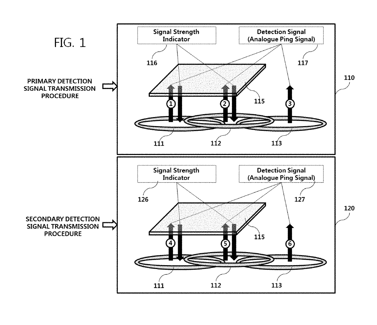
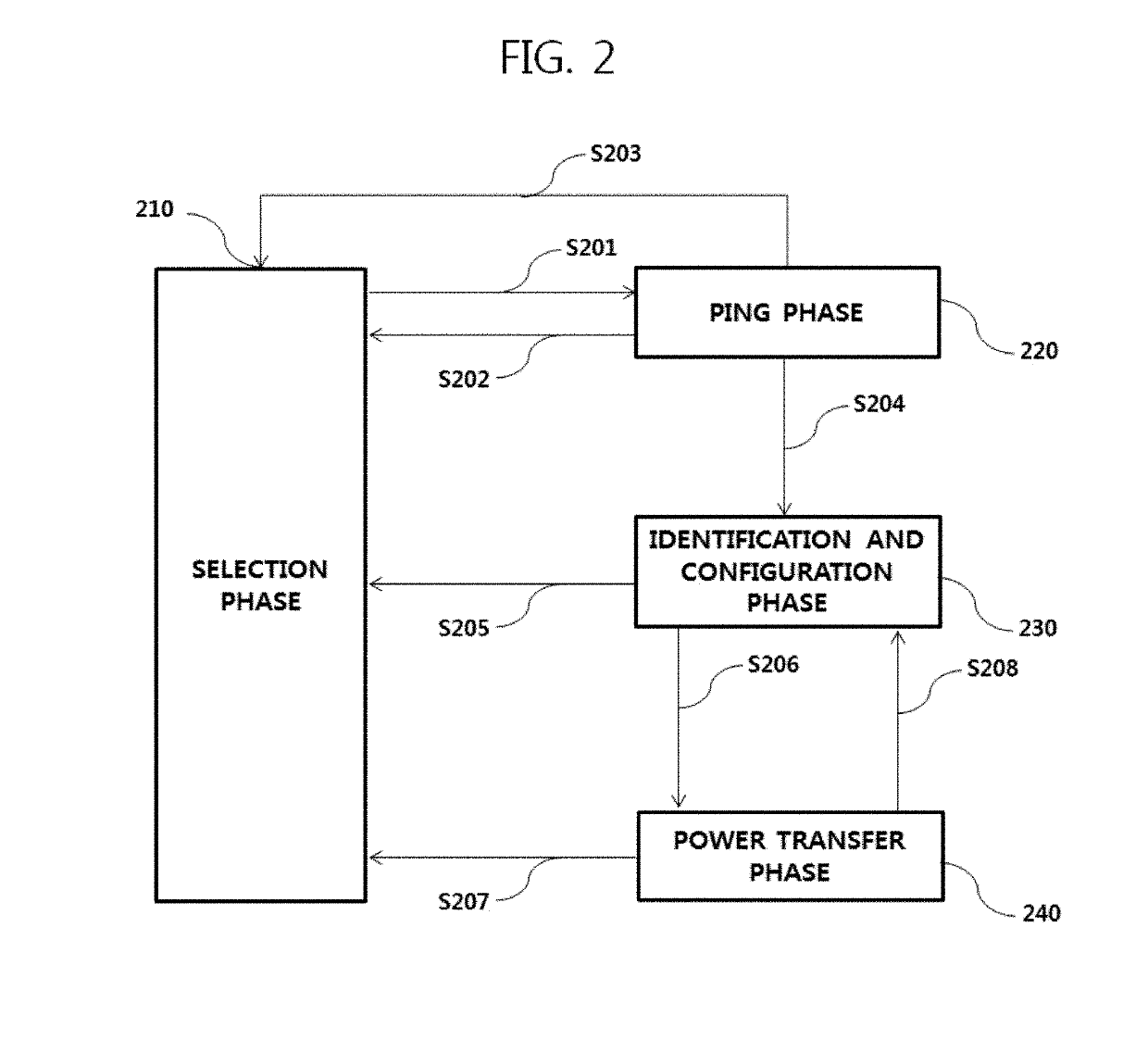
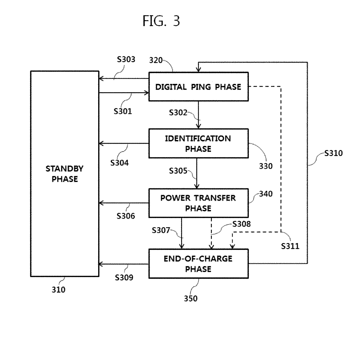
[0035]In the following description of the embodiments, for convenience of description, an apparatus of wirelessly transmitting power, which configures a wireless power transmission system, may be used in...


PUM

PropertyMeasurementUnit
transfer distanceaaaaaaaaaa
areaaaaaaaaaaa
poweraaaaaaaaaa

Abstract

A wireless power transmitter includes a shield; a first coil having a first hollow portion in a center area thereof; a second coil disposed below the first coil and having a second hollow portion in a center area thereof; and a third coil disposed below the first coil and having a third hollow portion in a center area thereof. Further, the first coil overlaps a portion of the second coil and a portion of the third coil, and the shield includes a first functional hole in a region corresponding to the first hollow portion; a second functional hole in a region corresponding to the second hollow portion; and a third functional hole in a region corresponding to the third hollow portion.

Description

CROSS REFERENCE TO RELATED APPLICATIONS[0001]This application is a Continuation of co-pending U.S. patent application Ser. No. 16 / 126,263 filed on Sep. 10, 2018, which is a Continuation of U.S. patent application Ser. No. 15 / 805,993 filed on Nov. 7, 2017 (now U.S. Pat. No. 10,097,038 issued on Oct. 9, 2018), which is a Continuation of U.S. patent application Ser. No. 15 / 367,925 filed on Dec. 2, 2016 (now U.S. Pat. No. 9,899,147 issued on Feb. 20, 2018), which claims the priority benefit under 35 U.S.C. § 119(a) to Korean Patent Application No. 10-2015-0181030 filed in the Republic of Korea on Dec. 17, 2015, all of which are hereby expressly incorporated by reference into the present application.BACKGROUND OF THE INVENTIONField of the Invention[0002]Embodiments relate to a wireless power transfer technology, and more particularly, to a method of mounting a transmission coil, which wirelessly transmits power, in a wireless power transmitter.Discussion of the Related Art[0003]With the ...

Claims


Application Information

Patent Timeline
Patent Type & Authority Applications(United States)
IPC IPC(8): H02J50/10H01F27/36H01F27/28H01F38/14
CPCH01F27/2885H02J50/10H01F38/14H02J50/90H01F27/367H02J7/025H02J50/12H02J50/70H02J50/40H01F27/366H01F27/36
Inventor LEEM, SUNG HYUN
Owner LG INNOTEK CO LTD
Why Eureka
Try Eureka