Method of inspecting a metal coating and a method for analytical control of a deposition electrolyte serving to deposit said metal coating

a metal coating and analytical control technology, applied in the direction of liquid/fluent solid measurement, instruments, cells, etc., can solve the problems of not being able to see whether the manufactured parts meet the requirements, the test of parts is very long, etc., and achieve the effect of high quality

Active Publication Date: 2014-11-25
ATOTECH DEUT GMBH
View PDF13 Cites 0 Cited by
  • Summary
  • Abstract
  • Description
  • Claims
  • Application Information

AI Technical Summary

Benefits of technology

[0010]Accordingly, it is the object of the present invention to find a method by means of which a fast, secure and, as a result thereof, reliable evaluation of the quality of a deposited layer of metal is made possible, said metal coating being either deposited alone onto a substrate or being a component part of a multilayered metal coating system. Moreover, it aims at allowing to control the deposition electrolyte used for depositing the metal coating in such a manner that the metal coatings deposited therewith have the desired quality. Finally, it aims at making it possible to directly draw deductions as to the monitoring and guiding of the deposition electrolyte in order to permit to keep the quality of the deposited coatings constant more easily.DESCRIPTION OF THE INVENTION
[0032]The deposited metal coating is preferably anodically dissolved in a special dissolution electrolyte. The dissolution electrolyte in particular contains ions of the metal to be deposited as well as at least one acid. Preferably, the composition of the dissolution electrolyte differs from the composition of the deposition electrolyte. The dissolution electrolyte should in particular contain no additive affecting the quality of the deposition such as the grain size. As a result, the working electrode provided with the metal coating is transferred into an electrolysis cell containing the dissolution electrolyte and comprising the counter electrode prior to performing the following method step b). The advantage of using the dissolution electrolyte is that the dissolution potential measured is much more constant than when using the deposition electrolyte. If the deposition electrolyte or an electrolyte also containing additives affecting the quality of the deposition is used to dissolve a metal coating deposited on the working electrode, one obtains respectively a dissolution potential that considerably differs from the dissolution potential obtained with a dissolution electrolyte that contains no such additives. Accordingly, the dissolution potential also significantly depends on the composition of the dissolution electrolyte.
[0045]Finally, the method of the invention for inspecting a metal coating, which involves the method steps a) through d), makes it possible to determine the potential differences between consecutive metal coatings in a multilayered system such as a multiple nickel coating system. Alternatively, a potential difference for consecutive coatings made from different metals such as from nickel and chromium may of course also be determined. For this purpose, the time-averaged values of the dissolution potentials of the consecutive layers, which have been deposited individually on the working electrode, and then the potential difference there between are determined by subtraction.

Problems solved by technology

Testing of the parts is very long though so that it takes a considerable amount of time before it can be seen whether the manufactured parts meet the requirements.

Method used


Image

  • Method of inspecting a metal coating and a method for analytical control of a deposition electrolyte serving to deposit said metal coating
  • Method of inspecting a metal coating and a method for analytical control of a deposition electrolyte serving to deposit said metal coating
  • Method of inspecting a metal coating and a method for analytical control of a deposition electrolyte serving to deposit said metal coating

Examples


example 1

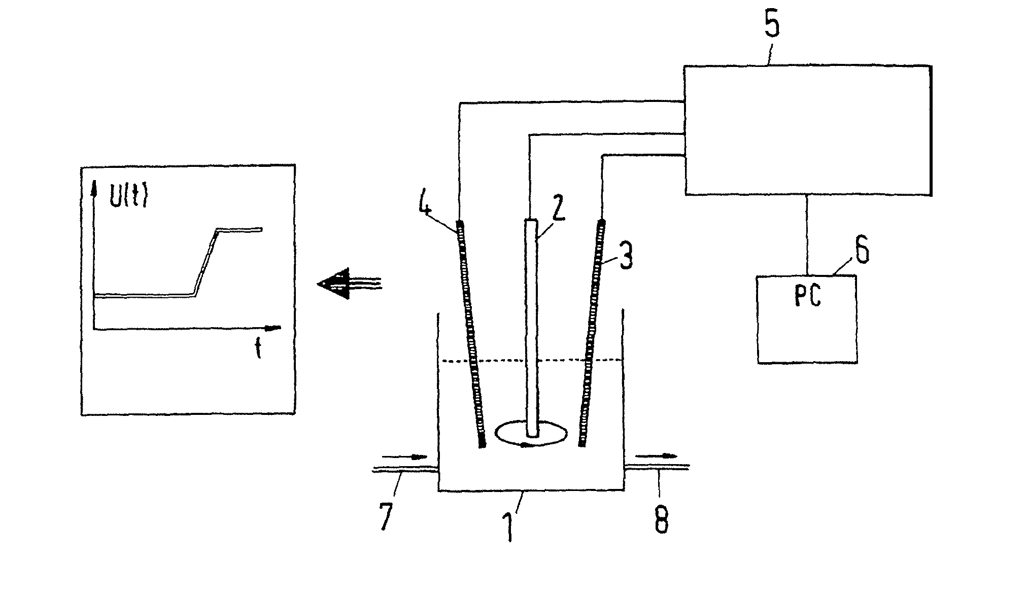
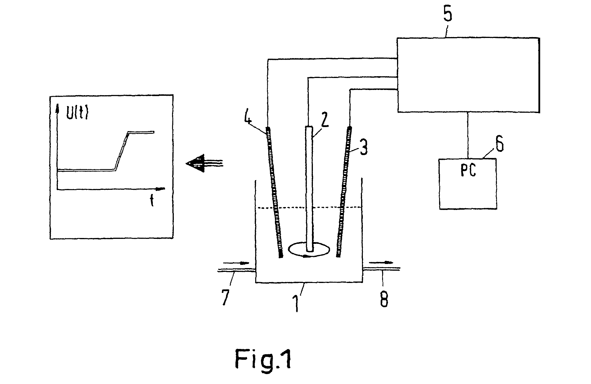
[0054]The measurement arrangement schematically shown in FIG. 1 comprises a measurement cell 1 in which there are located three electrodes: a working electrode 2, a counter electrode 3 and a reference electrode 4. The working electrode 1 is a rotating platinum electrode. The counter electrode 3 is a platinum wire and the reference electrode 4 is a silver wire that is coated with a silver chloride coating. The rotating platinum electrode 2 consists of a cylinder made from Teflon® (DuPont de Nemours), in the end side of which there is embedded a platinum disc of 0.071 cm2 in size. The cylinder rotates about its axis at 500 rpm. As a result, electrolyte contained in the measurement cell is circulated in a continuous flow to the surface of the platinum disc so that constant hydrodynamic conditions prevail at the platinum surface. The electrodes 2, 3, 4 are connected to a galvanostatic current source (galvanostat) 5. Thanks to the galvanostat 5, the current flowing between the platinum e...

example 2

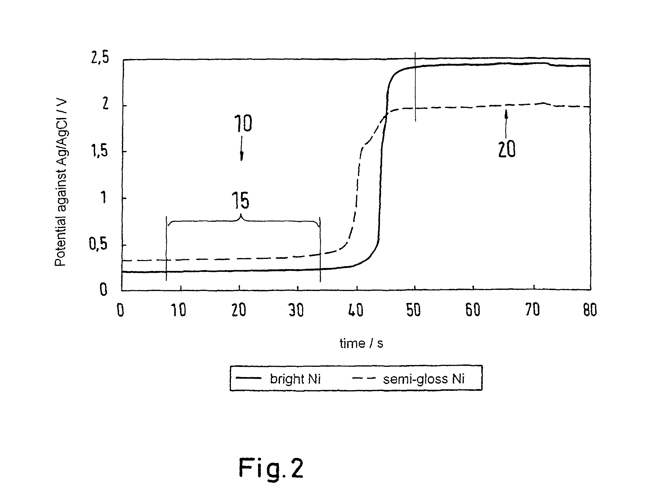
[0068]In another test design, the bright nickel coating and the semi-gloss nickel coating were deposited under different conditions and the thus obtained values for the dissolution potential after calculating the difference between the corresponding combinations of bright nickel coatings and semi-gloss nickel coatings were compared with values determined accordingly with the STEP test. The conditions for depositing the bright nickel coatings and the semi-gloss nickel coatings corresponded to those that had already been chosen in Example 1 if no other conditions are indicated herein after. The current density during deposition of the nickel coatings as well as the concentration of the additive determining the corrosion behaviour in the semi-gloss nickel were respectively varied. Tab. 1 compares the results of these tests against each other.

[0069]The difference values obtained with the method of the invention roughly coincide with the values obtained with the STEP test. Principally, i...

example 3

[0073]In another test, the influence of the electrolyte load, of the concentration of the semi-gloss nickel additive and of the current density during deposition of a semi-gloss nickel coating on the dissolution potential was examined. The electrolyte load is the charge imposed in the deposition electrolyte in the tank (15 l volume) to deposit semi-gloss nickel per volume unit, expressed in [A·h / l]. For this purpose, copper sheets were coated with semi-gloss nickel at different current densities (see Table 1). The dissolution potential was measured like in the Examples 1 and 2 with a current density of 26 A / dm2 on a platinum electrode rotating at 500 rpm. The potential was averaged as shown in Example 1.

[0074]For this purpose, a semi-gloss nickel electrolyte having a composition like in Example 1 was prepared in a bath tank holding 15 l. The additive was the same as described in Example 2. The additive concentration was at first 0 ml / l. Each rise in the additive concentration was ad...


PUM

PropertyMeasurementUnit
thicknessaaaaaaaaaa
thicknessaaaaaaaaaa
timeaaaaaaaaaa

Abstract

For fast and secure determination of the quality of a metal coating as well as of an electrolyte for depositing a metal, in particular for electrolytic deposition of nickel such as of semi-gloss nickel and bright nickel and for analytical control of the deposition electrolyte, a method of inspecting a metal coating is provided, which involves the following method steps: a) depositing the metal coating from a deposition electrolyte onto a working electrode; b) electrolytically dissolving the metal coating through anodic polarization of the working electrode with respect to a counter electrode, which is in electrolytic contact with the working electrode; c) recording an electrical dissolution potential at the working electrode over time, said potential occurring during a dissolution of the metal coating; and d) determining a time-averaged vale of the dissolution potential.

Description

FIELD OF THE INVENTION[0001]The present invention relates to a method of inspecting a metal coating which is either located alone on a substrate or which is a constituent part of a multi-layered metal coating system, as well as to a method of analytical control of a deposition electrolyte serving to deposit such a metal coating.PRIOR ART[0002]In order to protect metals from corrosion, it has been found advantageous to deposit a multiple nickel coating system on the surfaces thereof. Parts made from copper, brass or steel but also parts made from plastic material can be coated with this coating system for example. Typically, a thin coating of chromium is additionally deposited onto said multiple nickel coating system. The nickel coating serves for decorative purposes and also to protect the base material from corrosion.[0003]The multiple nickel coating system usually consists of a quite thick base layer made from semi gloss nickel. Its thickness may be 10-20 μm for example. Sulphur-f...

Claims


Application Information

Patent Timeline
Patent Type & Authority Patents(United States)
IPC IPC(8): G01N27/42C25D21/12C25D5/18
CPCG01N27/42C25D5/18C25D21/12C25D5/627G01N17/02G01N27/416
Inventor HARTMANN, PHILIPJONAT, MICHAELWUENSCHE, MATHIAS
Owner ATOTECH DEUT GMBH
Why Eureka
Try Eureka