Three-dimensional forming apparatus and three-dimensional forming method

a three-dimensional forming and forming apparatus technology, applied in additive manufacturing, solid and fluid additive manufacturing, additive manufacturing, etc., can solve problems such as sintering faults or melting faults, and achieve the effect of simple configuration and high productivity

Pending Publication Date: 2020-06-25
SEIKO EPSON CORP
View PDF2 Cites 0 Cited by
  • Summary
  • Abstract
  • Description
  • Claims
  • Application Information

AI Technical Summary

Benefits of technology

[0007]An advantage of some aspects of the invention is that it provides a three-dimensional forming apparatus with high productivity by driving a plurality of energy supply units synchronously with a simple configuration.
[0010]A sintered portion corresponding to one energy radiation unit is formed along one path of the relative movement of the head base relative to the stage by energy radiated from the energy radiation unit included in one head unit. Accordingly, the three-dimensional forming apparatus according to the application example includes the plurality of head units in the head base, and thus a plurality of sintered portions can be formed along one path of the head base. Accordingly, it is possible to shorten a relative movement path length between the head base and the stage along which a desired sintered region is formed, and thus it is possible to obtain the three-dimensional forming apparatus with high productivity.Application Example 2
[0012]A sintered portion corresponding to one head unit is formed along one path of the relative movement of the head base relative to the stage by energy radiated from the energy radiation unit to the sintered material supplied from the material ejection unit included in one head unit. Accordingly, the three-dimensional forming apparatus according to the application example includes the plurality of head units in the head base, and thus a plurality of sintered portions can be formed along one path of the head base. Accordingly, it is possible to shorten a relative movement path length between the head base and the stage along which a desired sintered region is formed, and thus it is possible to obtain the three-dimensional forming apparatus with high productivity.
[0019]A sintered portion corresponding to one energy radiation unit is formed along one path of the relative movement of the head base relative to the stage by energy radiated from the energy radiation unit included in one head unit. Accordingly, in the three-dimensional forming method according to the application example, the three-dimensional forming apparatus including the plurality of head units in the head base is used, and thus a plurality of sintered portions can be formed along one path of the head base. Accordingly, it is possible to shorten a relative movement path length between the head base and the stage along which a desired sintered region is formed, and thus it is possible to obtain the three-dimensional forming method with high productivity.
[0022]A sintered portion corresponding to one head unit is formed along one path of the relative movement of the head base relative to the stage by energy radiated from the energy radiation unit to the sintered material supplied from the material ejection unit included in one head unit. Accordingly, in the three-dimensional forming method according to the application example, the three-dimensional forming apparatus including the plurality of head units in the head base can be used, and thus a plurality of sintered portions can be formed along one path of the head base. Accordingly, it is possible to shorten a relative movement path length between the head base and the stage along which a desired sintered region is formed, and thus it is possible to obtain the three-dimensional forming method with high productivity.
[0027]According to this application example, the radiation of the energy can be focused on a supply material which is a target, and thus a three-dimensional fabricated object with good quality can be formed. For example, a radiated energy amount (power or a scanning speed) can be easily controlled according to a kind of sintered material, and thus the three-dimensional fabricated object with desired quality can be obtained.

Problems solved by technology

However, when an output of the laser is not high, there is a concern of a sintering fault or a melting fault occurring.

Method used


Image

  • Three-dimensional forming apparatus and three-dimensional forming method
  • Three-dimensional forming apparatus and three-dimensional forming method
  • Three-dimensional forming apparatus and three-dimensional forming method

Examples


first embodiment

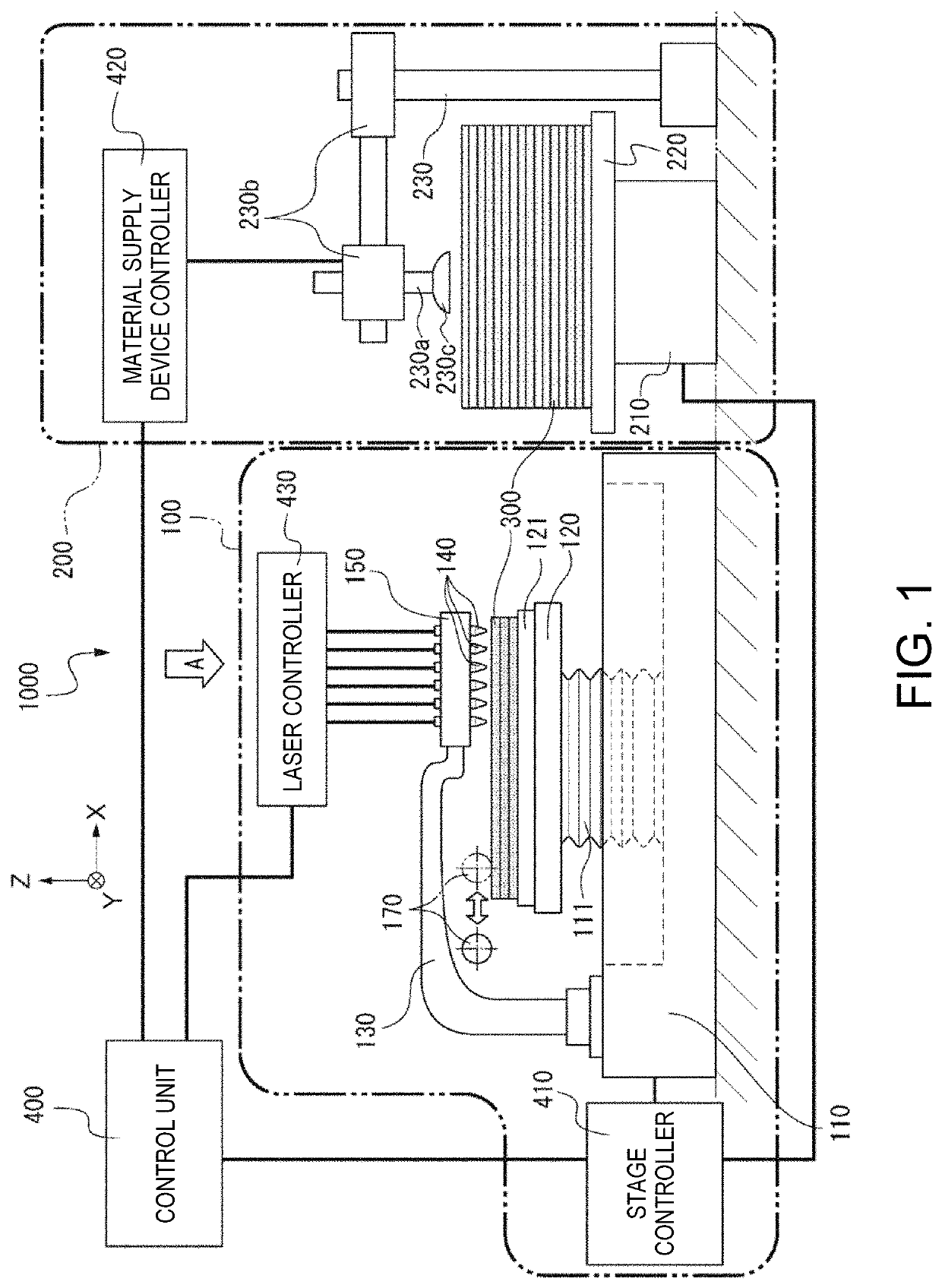
[0051]FIG. 1 is a schematic diagram illustrating the configuration of a three-dimensional forming apparatus according to a first embodiment. In the present specification, “three-dimensional forming” refers to forming a so-called stereoscopically fabricated object and includes, for example, forming a shape having a thickness even when the shape is a flat shape or a so-called two-dimensional shape.

[0052]A three-dimensional forming apparatus 1000 (hereinafter referred to as a forming apparatus 1000) illustrated in FIG. 1 includes a sintering device 100 that forms a three-dimensional fabricated object and a material supply device 200 serving as a material supply unit that supplies the sintering device 100 with supply material 300 (hereinafter referred to as a green sheet 300) called a so-called green sheet in which metal powder and a binder which are raw material of the three-dimensional fabricated object are kneaded and formed to a sheet shape.

[0053]The material supply device 200 inclu...

second embodiment

[0072]FIGS. 4A and 4B are schematic diagram illustrating the configuration of a three-dimensional forming apparatus according to a second embodiment. A three-dimensional forming apparatus 2000 (hereinafter referred to as a forming apparatus 2000) illustrated in FIG. 4A is different from the forming apparatus 1000 according to the first embodiment in the configuration of a material supply unit and the configuration of a head base and head units. Accordingly, the same reference numerals are given to the same constituent elements as those of the forming apparatus 1000 according to the first embodiment and the description thereof will be omitted.

[0073]As illustrated in FIGS. 4A and 4B, the forming apparatus 2000 includes a base 110, a stage 120 that can be moved in the illustrated X, Y, or Z direction or can be driven in a rotational direction about the Z axis by a driving device 111 serving as a driving unit included in the base 110, and a head base supporting unit 130 that has one end...

third embodiment

[0096]A three-dimensional forming method of forming a three-dimensional fabricated object using the three-dimensional forming apparatus 1000 according to the first embodiment will be described according to a third embodiment. FIG. 11 is a flowchart illustrating the three-dimensional forming method according to the third embodiment. FIG. 12 is a schematic diagram illustrating the configuration of a green sheet forming apparatus that forms the green sheet 300. FIGS. 13A, 13B, 14A, and 14B are schematic plan views and sectional views illustrating steps of the three-dimensional forming method according to the embodiment. FIGS. 15E and 15F are external perspective views and schematic sectional views illustrating steps of the three-dimensional forming method according to the embodiment.

Three-Dimensional Fabrication Data Acquisition Process

[0097]As illustrated in FIG. 11, in the three-dimensional forming method according to the embodiment, a three-dimensional fabrication data acquisition p...


PUM

PropertyMeasurementUnit
sizeaaaaaaaaaa
areaaaaaaaaaaa
lengthaaaaaaaaaa

Abstract

A three-dimensional forming apparatus includes: a stage; a material supply unit that supplies the stage with a sintered material including metal powder and a binder, a head unit that includes an energy radiation unit supplying energy capable of sintering the sintered material to the sintered material supplied by the material supply unit, a head base that holds a plurality of the head units, and a driving unit that is capable of three-dimensionally moving the head base relative to the stage.

Description

CROSS-REFERENCE TO RELATED APPLICATIONS[0001]This application is a Continuation of U.S. patent application Ser. No. 15 / 163,287, filed May 24, 2016, which claims priority to Japanese Patent Application No. 2015-106177, filed May 26, 2015. The foregoing applications are hereby incorporated by reference in their entirety.BACKGROUND1. Technical Field[0002]The present invention relates to a three-dimensional forming apparatus and a three-dimensional forming method.2. Related Art[0003]In the related art, a method described in JP-A-2008-184622 is disclosed as a manufacturing method of simply forming a three-dimensional shape using a metal material. The three-dimensional fabricated object manufacturing method disclosed in JP-A-2008-184622 is used to form a metal paste, which includes metal powder, a solvent, and an adhesion enhancer in a raw material, in material layers of a layered state. Then, metal sintered layers or metal melted layers are formed by radiating a light beam to material la...

Claims


Application Information

Patent Timeline
Patent Type & Authority Applications(United States)
IPC IPC(8): B29C64/165B22F3/105
CPCB22F3/1055Y02P10/295B22F2003/1056B33Y10/00B33Y30/00B29C64/165B22F3/003B22F10/00B22F10/16B22F12/22Y02P10/25
Inventor KATAKURA, TAKAHIROMIYASHITA, TAKESHIKAMAKURA, TOMOYUKITAKEUCHI, TETSUHIKO
Owner SEIKO EPSON CORP
Why Eureka
Try Eureka