Parallel read with source-clear operation

a parallel read and source clearing technology, applied in the field of computer graphics, can solve the problems of inefficient two-step sequential process of reading followed by source clearing, data and data rate putting additional burden on memory systems,

Inactive Publication Date: 2004-09-21
ORACLE INT CORP
View PDF5 Cites 16 Cited by
  • Summary
  • Abstract
  • Description
  • Claims
  • Application Information

AI Technical Summary

Problems solved by technology

This consistent increase in data and data rates places additional burden on the memory systems that form an integral part of the graphics system.
This two-step sequential process of reading followed by source clearing is inefficient.

Method used


Image

  • Parallel read with source-clear operation
  • Parallel read with source-clear operation
  • Parallel read with source-clear operation

Examples


Embodiment Construction

Computer System--FIG. 1

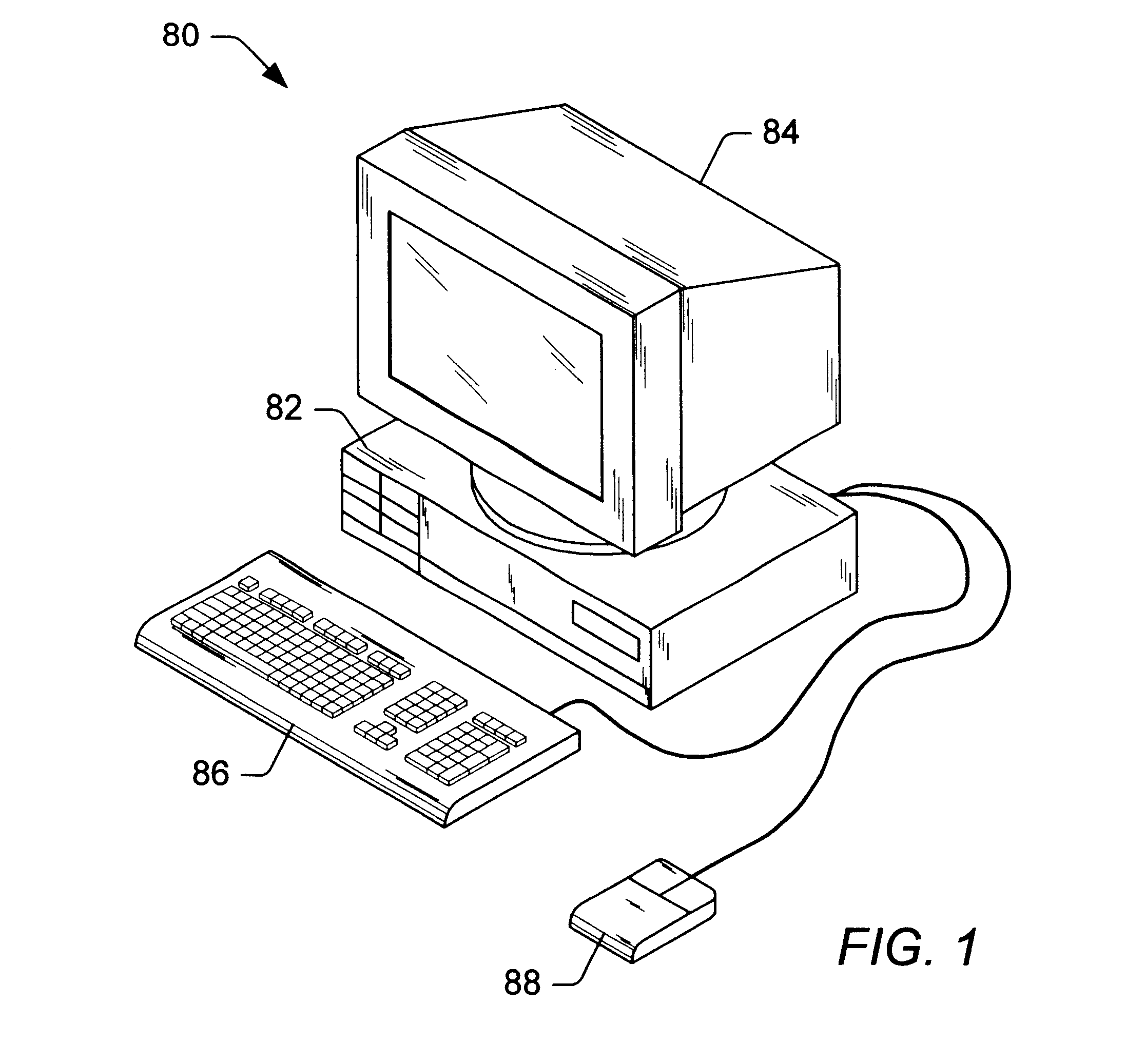
Referring now to FIG. 1, one embodiment of a computer system 80 that includes a graphics system is shown. The graphics system may be comprised in any of various systems, including computer systems, network PCs, Internet appliances, televisions (including HDTV systems and interactive television systems), personal digital assistants (PDAs), virtual reality systems, and other devices which display 2D and / or 3D graphics, among others.

As shown, the computer system 80 comprises a system unit 82 and a video monitor or display device 84 coupled to the system unit 82. The display device 84 may be any of various types of display monitors or devices (e.g., a CRT, LCD, or gas-plasma display). Various input devices may be connected to the computer system, including a keyboard 86 and / or a mouse 88, or other input device (e.g., a trackball, digitizer, tablet, six-degree of freedom input device, head tracker, eye tracker, data glove, or body sensors). Application software may...


PUM


Abstract

A memory interface controls read and write accesses to a memory device. The memory device includes a level-one cache, level-two cache and storage cell array. The memory interface includes a data request processor (DRP), a memory control processor (MCP) and a block cleansing unit (BCU). The MCP controls transfers between the storage cell array, the level-two cache and the level-one cache. In response to a read request with associated read clear indication, the DRP controls a read from a level-one cache block, updates bits in a corresponding dirty tag, and sets a mode indicator of the dirty tag to a the read clear mode. The modified dirty tag bits and mode indicator are signals to the BCU that the level-one cache block requires a source clear operation. The BCU commands the transfer of data from a color fill block in the level-one cache to the level-two cache.

Description

1. Field of the InventionThis invention relates generally to the field of computer graphics and, more particularly, to memory controller architecture.2. Description of the Related ArtWith each new generation of graphics system, there is more image data to process and less time in which to process it. This consistent increase in data and data rates places additional burden on the memory systems that form an integral part of the graphics system. Attempts to further improve graphics system performance are now running up against the limitations of these memory systems in general, and memory device limitations in particular.In order to provide memory systems with increased data handling rates and capacities, system architects may employ consistently higher levels of integration. One example of increased integration is the 3D-RAM family of memories manufactured by the Mitsubishi Corporation. A 3D-RAM memory may include multiple banks of DRAM main storage with level one and level two cache...

Claims


Application Information

Patent Timeline
Patent Type & Authority Patents(United States)
IPC IPC(8): G06F12/08G09G5/395G09G5/393G09G5/36
CPCG06F12/0891G06F12/0897G09G5/363G09G5/393G09G5/395G06F12/0875G09G2360/121G09G2360/126G09G2360/127
Inventor LAVELLE, MICHAEL G.KUBALSKA, EWA M.TANG, YAN Y.
Owner ORACLE INT CORP
Why Eureka
Try Eureka