System and method for optically communicating information between a display and a camera

a technology of optical communication and display, applied in the field of optical communication of information, can solve the problems of large degree of human intervention required to facilitate the download, inaccurate and incomplete data transmission, and few techniques currently available that permit optical communication between a display and a camera, so as to maximize the probability of a strong correlation for each pixel and minimize flicker

Inactive Publication Date: 2004-09-28
MICROSOFT TECH LICENSING LLC
View PDF10 Cites 48 Cited by
  • Summary
  • Abstract
  • Description
  • Claims
  • Application Information

AI Technical Summary

Benefits of technology

Moreover, the present invention also includes stabilizing video images of the display in the event that the display is a cathode ray tube (CRT) design. More specifically, the present invention includes an aggregation technique that obtains a series of camera images and produces a stabilized aggregated image to minimize flicker caused by the display being refreshed. In addition, the present invention includes a method for using either a stereo camera or a monocular camera to determine a pose of the display (relative to the cameras). In a preferred embodiment, the technique uses a stereo camera to measure pose and includes using a random localization pattern displayed on the screen to be observed by the stereo camera in order to maximize the probability of a strong correlation for each pixel. In an alternate embodiment, a monocular camera is used to measure pose by determining camera calibration parameters, detecting three or more points on the display, determining the relative positions on a plane of these points in physical (or real) units and computing the display pose relative to the camera using correlation techniques well-known to those of ordinary skill in the art. The present invention also includes a system for optically communicating information between a display and a camera using the above-described method.

Problems solved by technology

Unfortunately, there are few techniques currently available that permit optical communication between a display and a camera.
One disadvantage, however, of this technique is that a large degree of human intervention is required to facilitate the download.
In particular, the user must hold the watch up to the display for the duration of the download, which can be tiring for the user and lead to inaccurate and incomplete data transmission.
In addition, this technique and others have the disadvantage of not being able to automatically determine the spatial location (or pose) of the display relative to the camera observing the display.

Method used


Image

  • System and method for optically communicating information between a display and a camera
  • System and method for optically communicating information between a display and a camera
  • System and method for optically communicating information between a display and a camera

Examples


Embodiment Construction

In the following description of the invention, reference is made to the accompanying drawings, which form a part thereof, and in which is shown by way of illustration a specific example whereby the invention may be practiced. It is to be understood that other embodiments may be utilized and structural changes may be made without departing from the scope of the present invention.

I. Exemplary Operating Environment

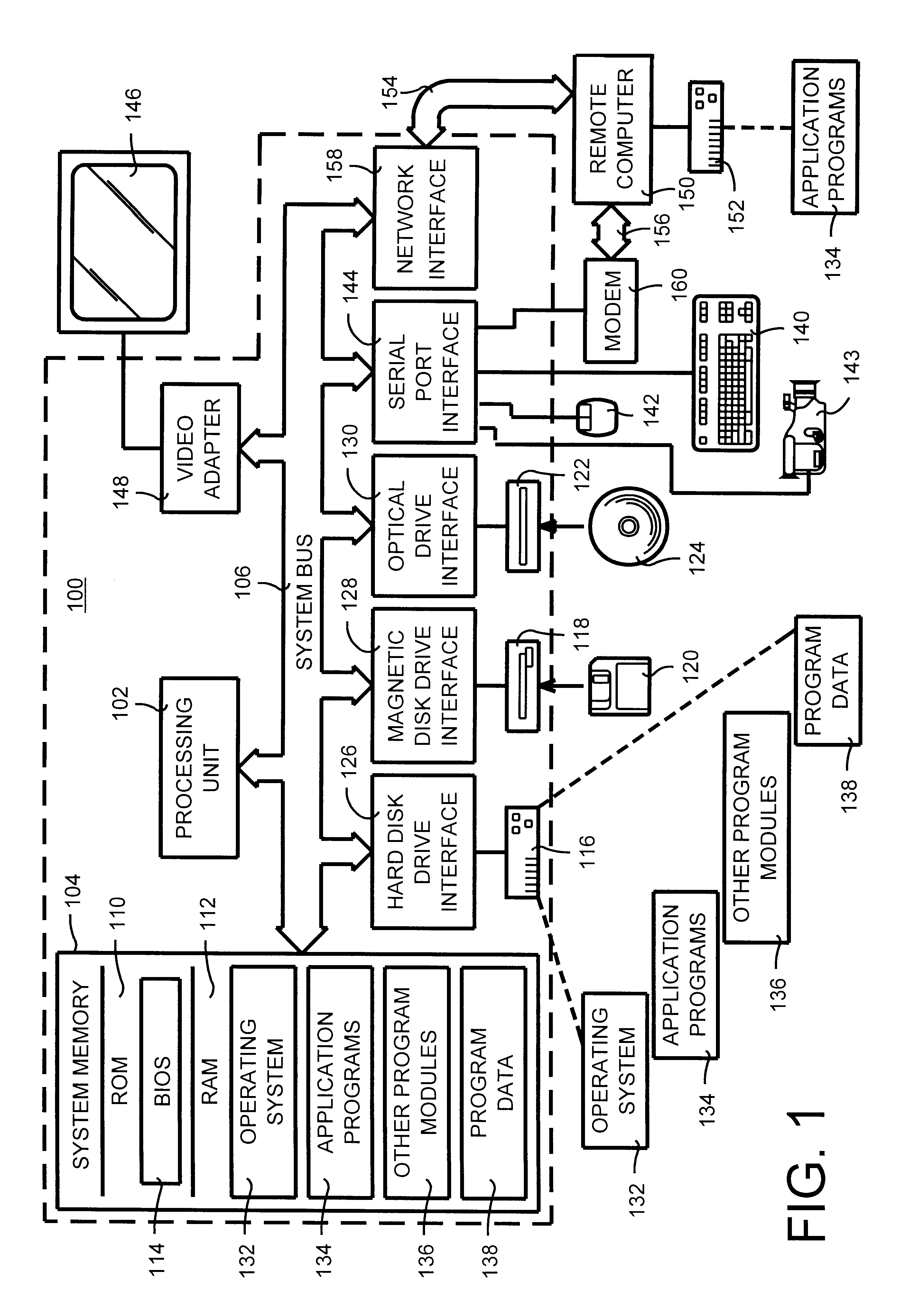
FIG. 1 and the following discussion are intended to provide a brief, general description of a suitable computing environment in which the optical communication system and method of the present invention may be implemented. Although not required, the invention will be described in the general context of computer-executable instructions (such as program modules) being executed by a computer. Generally, program modules include routines, programs, objects, components, data structures, etc. that perform particular tasks or implement particular abstract data types. Moreover, those ...


PUM


Abstract

A system and a method for optically communicating information between a display and a camera that is observing the display. In general, the transmission of information is unidirectional in a direction from the display to the camera. The display transmits information to the camera that is observing the display by displaying a series of symbols and images (such as an alphabet) on the display. Information (such as a network address of the display or camera) may be transmitted to the camera without any prior shared knowledge between the two. The present invention also is capable of determining a spatial location (or pose) of the display (relative to a camera observing the display) by observing a pattern presented on the display and using well-known correlation techniques.

Description

BACKGROUND OF THE INVENTION1. Field of the InventionThe present invention relates in general to an optical communication of information and more particularly to a system and a method for optically communicating information between a display and a camera that is observing the display.2. Related ArtOptical communication between an image source (such as a display) and an image detector (such as a camera) is desirable and has several applications. By way of example, if a computer network contains several devices and sensors within a large physical space, the addition of a new device (such as a display or a camera) could be greatly simplified if the display and the camera were in optical communication. The display and camera would simply establish an optical communication link and transmit information (such as a network address). In this manner a new device could be connected to the computer network automatically and without human intervention.Unfortunately, there are few techniques curr...

Claims


Application Information

Patent Timeline
Patent Type & Authority Patents(United States)
IPC IPC(8): H04N5/232H04N5/247
CPCH04N5/2224H04N5/23203H04N5/247H04N23/66H04N23/90
Inventor BRUMITT, BARRETT L.SHAFER, STEVEN A. N.HARRIS, STEPHEN C.
Owner MICROSOFT TECH LICENSING LLC
Why Eureka
Try Eureka