
Plasma display device configured to change the driving waveform according to temperature and a driving method thereof

a technology of display device and temperature, applied in the direction of static indicating device, heat measurement, instruments, etc., can solve the problems of flickering, i, twinkle, etc., and achieve the effect of shortening the duration

Inactive Publication Date: 2012-05-29
SAMSUNG SDI CO LTD
View PDF20 Cites 0 Cited by
  • Summary
  • Abstract
  • Description
  • Claims
  • Application Information

AI Technical Summary

Benefits of technology

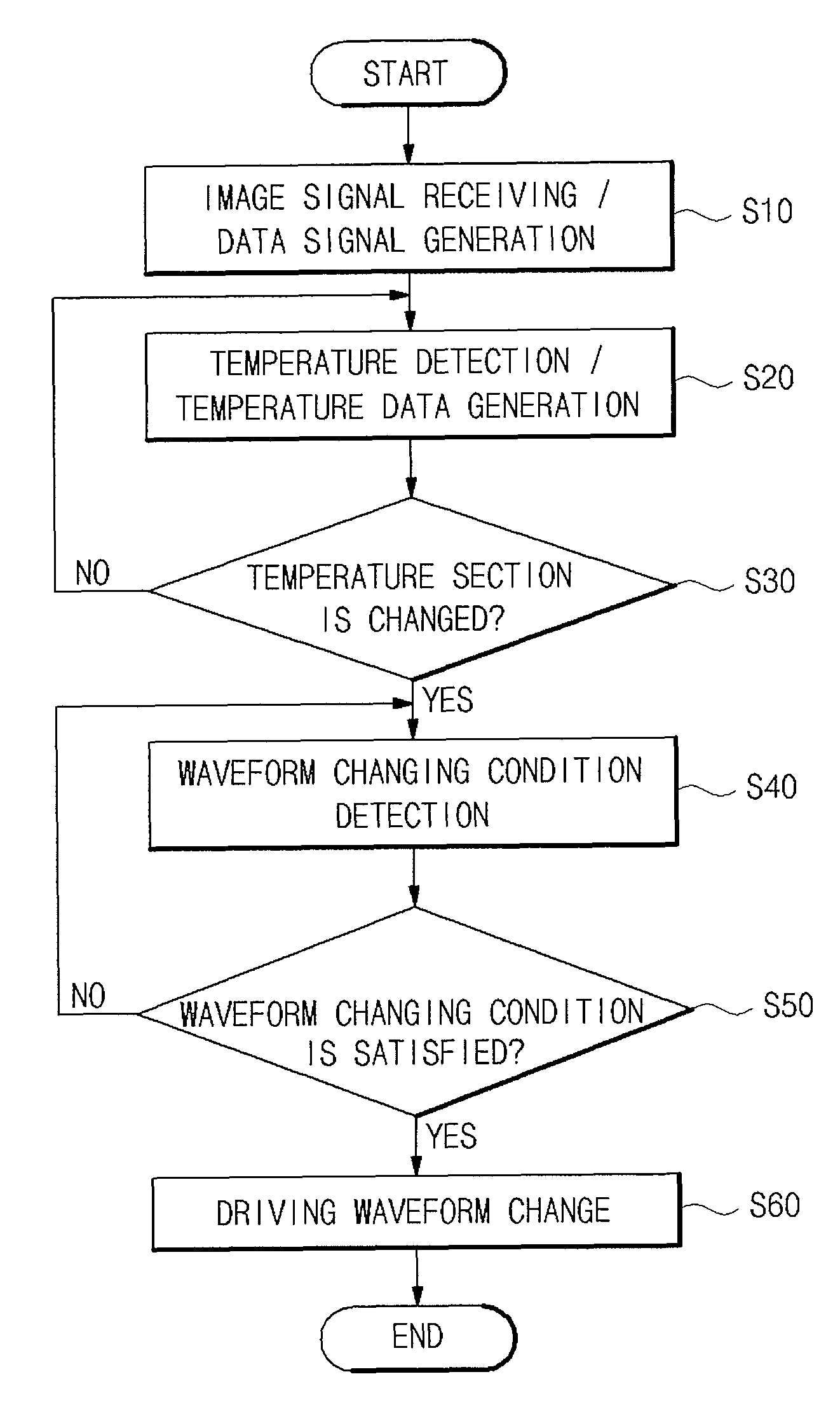
[0007]An aspect of an embodiment of the present invention is to provide a plasma display device and a driving method thereof that can change and select a changing time of a driving waveform so as to minimize production of flicker when the plasma display device is driven by a different driving waveform according to the temperature.
[0008]Another aspect of an embodiment of the present invention is to provide a plasma display device and a driving method thereof that can minimize production of flicker and the recognition of flicker by users, using various methods of determining a supply time of a driving waveform to minimize the flicker when the driving waveform is changed.
[0009]Another aspect of an embodiment of the present invention is to provide a plasma display device and a driving method thereof that can provide a range of the supply time of the driving waveform that prevents the production of misfiring while minimizing the production of flicker so as to provide a good quality image.

Problems solved by technology

However, dividing the temperature of the display panel into several temperature or environment sections causes another problem.
A typical problem is that flicker, i.e., twinkle, occurs when the driving waveform is changed depending on the temperature section.

Method used


Image

  • Plasma display device configured to change the driving waveform according to temperature and a driving method thereof
  • Plasma display device configured to change the driving waveform according to temperature and a driving method thereof
  • Plasma display device configured to change the driving waveform according to temperature and a driving method thereof

Examples


Embodiment Construction

[0049]In the following detailed description, only certain exemplary embodiments of the present invention have been shown and described, simply by way of illustration. As those skilled in the art would realize, the described embodiments may be modified in various different ways, all without departing from the spirit and scope of the present invention. Accordingly, the drawings and description are to be regarded as illustrative in nature and not restrictive. Like reference numerals designate like elements throughout the specification.

[0050]In addition, embodiments of the present invention are described for a single scan type, ADS (Address Display Separate), three electrode surface discharge type structure as an example, but the present invention is not limited thereto.

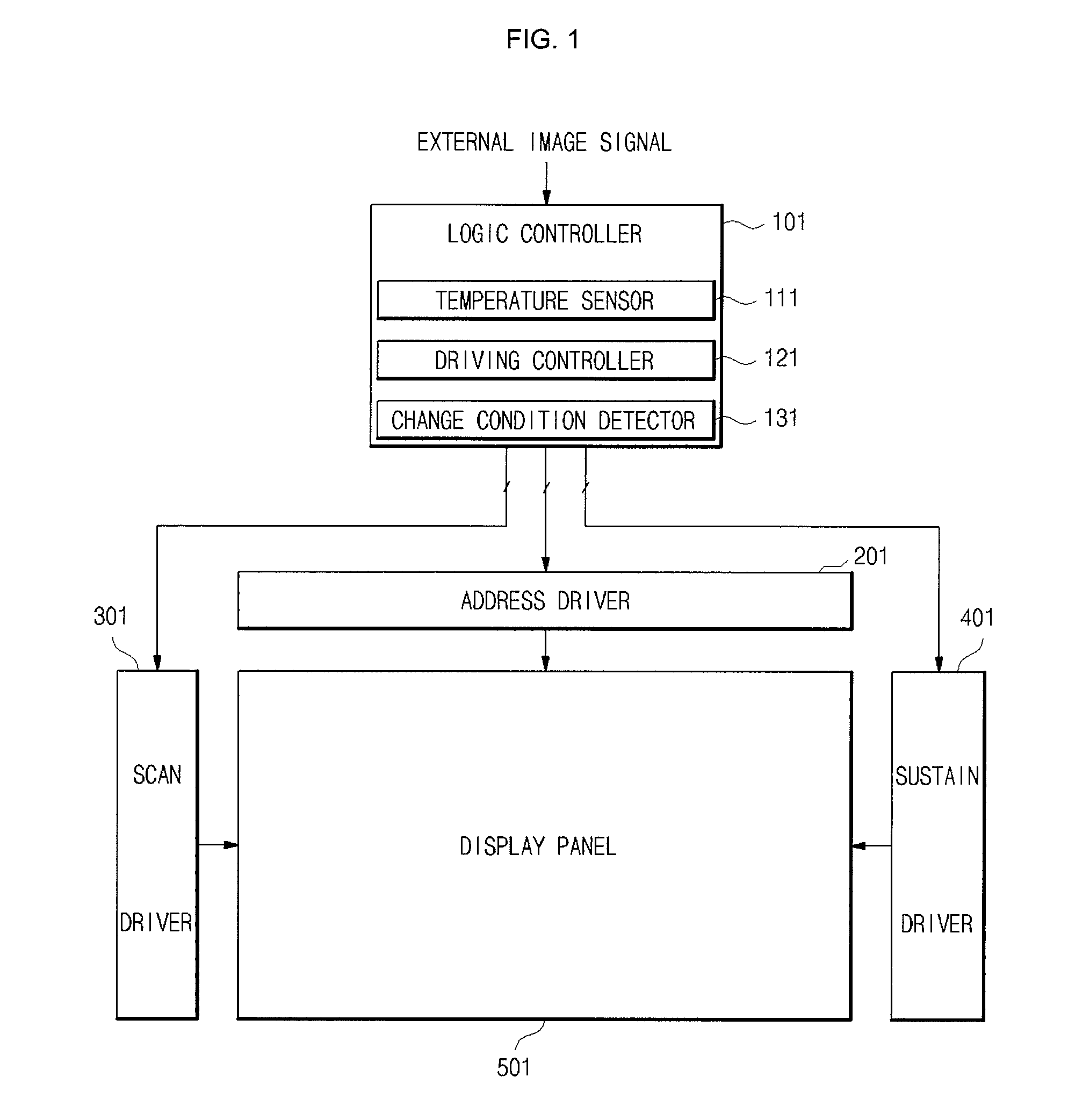
[0051]FIG. 1 is a diagram illustrating a plasma display device according to an embodiment of the present invention;

[0052]Referring to FIG. 1, the plasma display device includes a logic controller 101, drivers 201, 301 an...


PUM


Abstract

A plasma display device including: a display panel for displaying an image according to a driving signal converted from an external image signal; a logic controller for measuring a temperature of the display panel for comparison with a temperature section information having at least two temperature sections, generating a driving control signal for changing the driving signal when the temperature of the display panel changes to a temperature of a different temperature section, and calculating a changing condition included in the driving control signal for determining a changing time of the driving signal; and a driver for supplying the driving signal that is changed according to the temperature section at the changing time determined by the changing condition of the driving control signal.

Description

CLAIM FOR PRIORITY[0001]This application claims priority to and the benefit of Korean Patent Application No. 10-2007-0040862 filed on Apr. 26, 2007 in the Korean Intellectual Property Office (KIPO), the entire content of which is incorporated herein by reference.BACKGROUND OF THE INVENTION[0002]1. Field of the Invention[0003]The present invention relates to a plasma display device and a driving method thereof.[0004]2. Description of the Related Art[0005]The plasma display panel (or device) displays an image by emitting electrons with a high voltage, exciting inert gas sealed between substrates of the display panel by the emitted electrons to emit ultra violet rays, and exciting phosphors to emit visible ray. Due to such characteristics, the plasma display panel is relatively sensitive to the temperature of the display panel and the environment when being driven, compared with other flat display devices. Recently, the plasma display panel displays high quality images regardless of te...

Claims


Application Information

Patent Timeline
Patent Type & Authority Patents(United States)
IPC IPC(8): G09G5/00
CPCG09G3/2927G09G3/294G09G2320/0247G09G2320/041G09G2340/16G09G2360/16G09G3/296G01K1/00
Inventor JANG, HYUKJUN
Owner SAMSUNG SDI CO LTD
Learn More