
Distributed architecture for a base station transceiver subsystem having a radio unit that is remotely programmable

a technology of distributed architecture and base station, applied in the field of wireless communication systems, can solve the problems of reducing transmission power, reducing receiver sensitivity, and suffering from undesirable power loss of cables of this length

Inactive Publication Date: 2004-10-05
SAMSUNG ELECTRONICS CO LTD
View PDF24 Cites 90 Cited by
  • Summary
  • Abstract
  • Description
  • Claims
  • Application Information

AI Technical Summary

Problems solved by technology

Cables of these lengths suffer from undesirable power losses.
Minimizing these power losses is important because such losses in the cables degrade the receiver sensitivity and reduce transmission power.
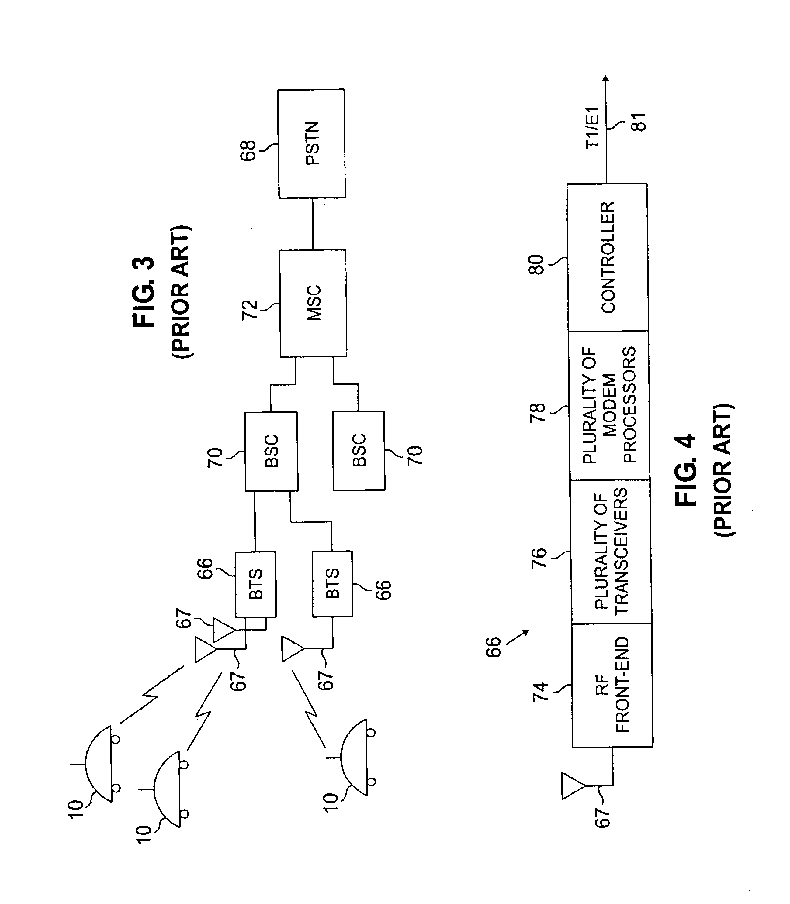
Other problems are associated with transmitted RF signals between the LNA / PA unit 74 and the BTS 66, such as power losses, system noise, and mechanical clutter.
Furthermore additional complex circuitry either or both in the RF front-end module and the transceiver may be required to automatically compensate for the wide range of cable losses that arise in different installation scenarios due to varying cable lengths.
Such problems get more severe as the operating RF Frequencies are allocated in the increasingly higher frequency bands.
Power losses in the cable work against reception as well, reducing the ability of the receiver to detect received signals.
Thus, RF cable losses incurred on both the transmit and receive paths result in poorer than desired transmission efficiency and lower than desired receiver sensitivity, making the use of relatively thick (high conductance) coaxial cables necessary to minimize loss.
Generally, in a wireless environment, wherein radio frequencies are transmitted through air, interferences are inevitable.
That is, unless a transmitting antenna is directly in the line-of-site of the receiving antenna and no obstacles, such as trees, buildings, rock formations, water towers, etc., are in the way, then reflections will cause fading and multipath signals.
Increasing the number of antennas creates an "eye-sore" for the public and is not desirable.
Neither design is suitable for use in a compact BTS system due to high power loss in the combiners and the inability to provide diversity reception.
Cable losses degrade the receiver sensitivity and reduce the transmit power.
Previously, in units where the PA is mounted on the pole, the output power attenuation could be detected, but the operator could not determine if the problem was in the PA module or the MU.

Method used


Image

  • Distributed architecture for a base station transceiver subsystem having a radio unit that is remotely programmable
  • Distributed architecture for a base station transceiver subsystem having a radio unit that is remotely programmable
  • Distributed architecture for a base station transceiver subsystem having a radio unit that is remotely programmable

Examples


Embodiment Construction

In the description which follows, exemplary preferred embodiments of the invention are described for a Pico base station transceiver subsystem architecture. However, it will be understood that the present invention may be applied to any base station transceiver subsystem architecture in a wireless communication system, including, but not limited to, macro and micro base station transceiver subsystems.

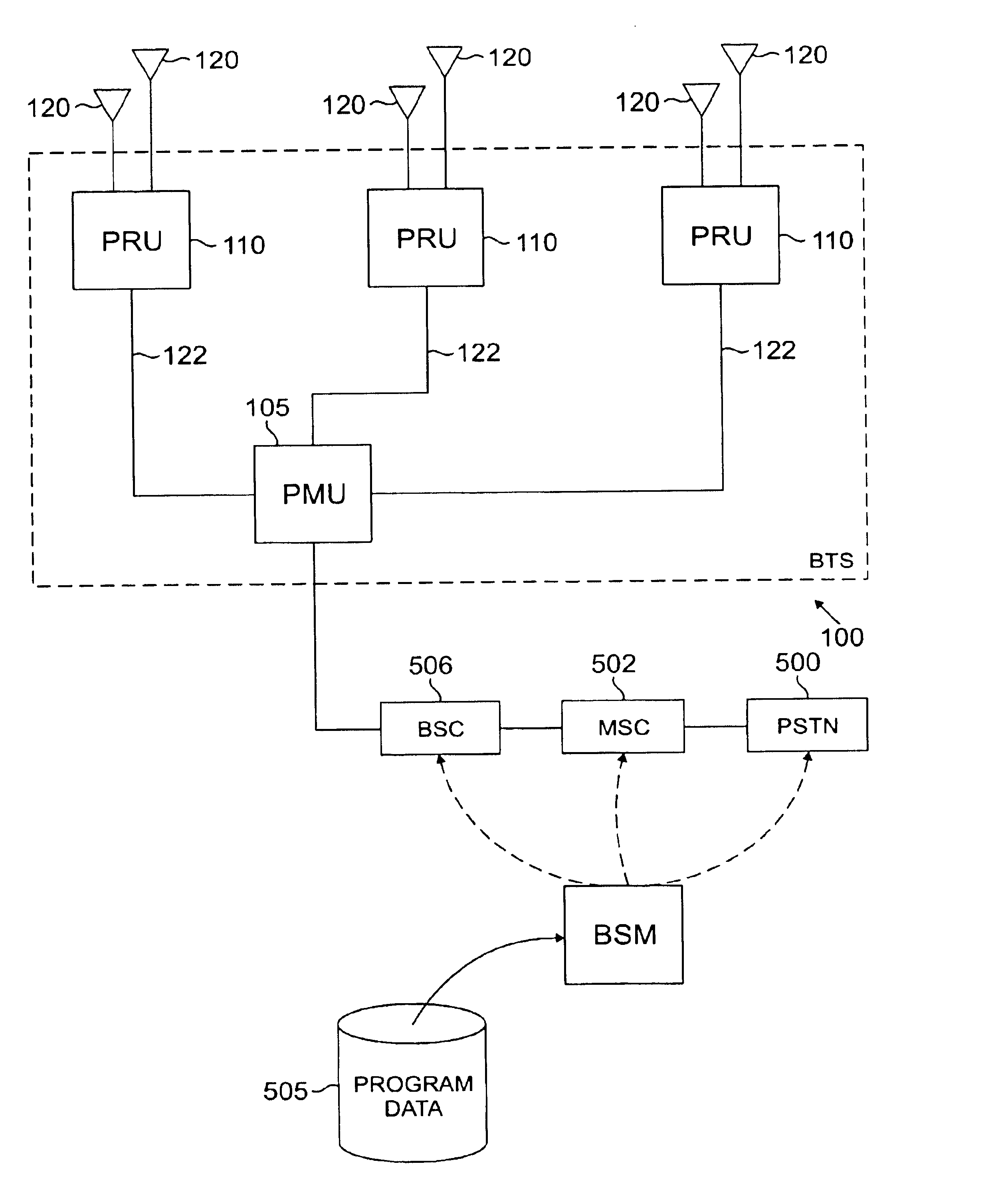
FIG. 9 illustrates the basic idea underlying a base station transceiver subsystem (BTS) architecture according to an exemplary embodiment of the present invention--the BTS is separated into two units, the Pico-BTS Radio Unit 110 and the Pico-BTS Main Unit 105. In the exemplary system illustrated in FIG. 9, a Pico-BTS comprises the Pico-BTS architecture 100 which is divided into the Pico-BTS Main Unit ("Main Unit System," PMU, or MU) 105 which may be located, as shown, at the base of a pole, tower, or other support structure 115, and the Pico-BTS Radio Unit ("Radio Unit System," PRU or R...


PUM


Abstract

A telecommunication base station transceiver subsystem that can be easily configured to provide single or multi-carrier frequency service. The base station is divided into a main unit and a radio unit such that the radio unit is positioned proximate to the antennas and the main unit is remotely located from the radio unit. A single base station transceiver can provide service via multiple wireless protocols, such as CDMA, TDMA, GSM or Analog. The base station transceiver .can also operate on various transmit / receive frequencies as well as variable transmit power settings. Furthermore, the base station transceiver can be reprogrammed, reconfigured and / or statused by a network operations center.

Description

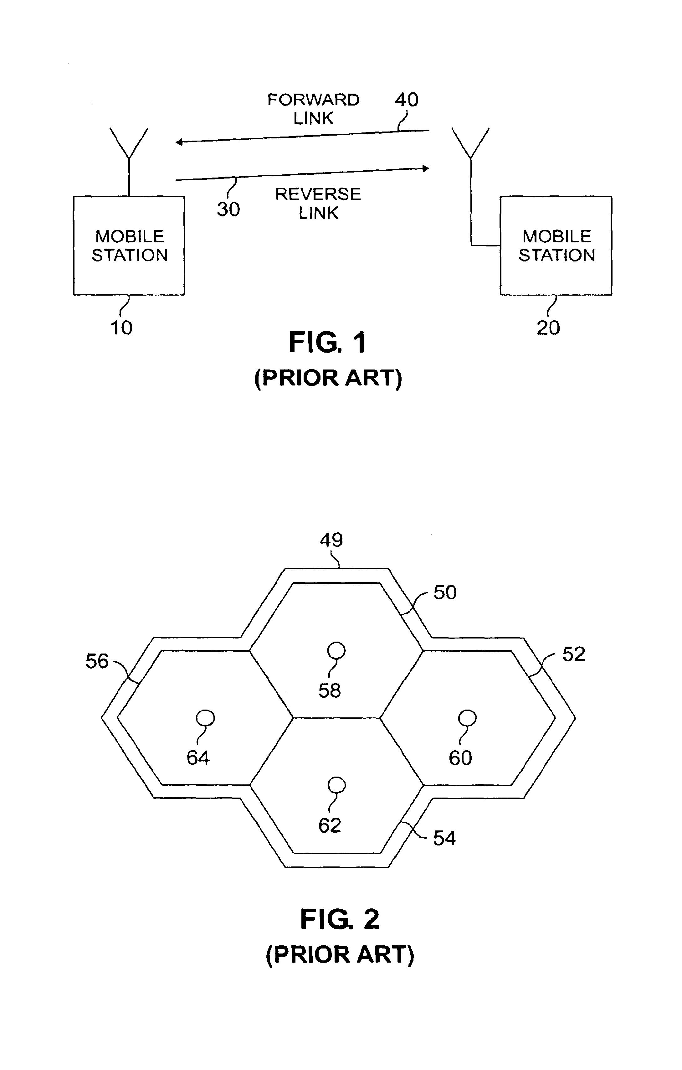
1. Field of the InventionThe present invention generally relates to wireless communication systems and, more particularly, to base station transceiver subsystems used in a Code Division Multiple Access (CDMA) network or other digital and analog telecommunication systems.2. Description of Related ArtFIG. 1 (prior art) is a block-flow diagram which graphically represents a wireless communication system. From FIG. 1 it is seen that a basic wireless communication system comprises a mobile station 10, a base station 20, a reverse link 30, which represents the electromagnetic wave communication link transmitted from mobile station 10 to base station 20, and a forward link 40 which represents the electromagnetic wave communication link transmitted from base station 20 to mobile station 10.FIG. 2 (prior art) shows a cell grid and cell sites. In a wireless communication system based on the general cellular principle, a service area 49 is divided geographically, into a number of small areas 5...

Claims


Application Information

Patent Timeline
IPC IPC(8): H04Q7/30H04W88/08
CPCH04W88/085Y02D30/70
Inventor CSAPO, JOHN S.JOHNSON, MITCHELLBRADY, BRUCE F.CHIEN, MARK C.RAPP, ROBERT A.
Owner SAMSUNG ELECTRONICS CO LTD
Learn More