Liquid crystal dispensing apparatus having controlling function of dropping amount caused by controlling tension of spring

a technology of liquid crystal dispensing apparatus and spring, which is applied in the direction of liquid handling, instruments, packaged goods, etc., can solve the problems of increasing liquid crystal fabrication costs, reducing fabrication efficiency, and excessive consumption of liquid crystal 14

Inactive Publication Date: 2004-10-19
LG DISPLAY CO LTD
View PDF160 Cites 20 Cited by
  • Summary
  • Abstract
  • Description
  • Claims
  • Application Information

AI Technical Summary

Benefits of technology

Accordingly, the present invention is directed to provide a liquid crystal dispensing apparatus for directly dropping liquid crystal onto a glass substrate that substantially obviates one or more of the problems due to limitations and disadvantages of the related art.
To achieve these and other advantages and in accordance with the purpose of the present invention, as embodied and broadly described herein, there is provided a liquid crystal dispensing apparatus having a liquid crystal container for holding a liquid crystal. The liquid crystal container is inside a case. A needle sheet is disposed on a lower portion of the liquid crystal container. The needle sheet includes an opening through which liquid crystal in the liquid crystal container is discharged. A movable needle is inserted into the liquid crystal container. A spring in a receiving case biases the needle toward the opening such that the opening tends to close. A tension controller connected to the receiving case controls the tension of the spring by controlling the spring length. A solenoid, beneficially with the aid of a bar magnetic, selectively produces a magnetic force that moves the needle away from the opening. A nozzle disposed on a lower portion of the liquid crystal container emits liquid crystal when the opening is open.

Problems solved by technology

While generally successful, there are problems with pressure injecting liquid crystal 14.
This decreases fabrication efficiency.
Second, liquid crystal 14 consumption is excessive.
This increases liquid crystal fabrication costs.

Method used


Image

  • Liquid crystal dispensing apparatus having controlling function of dropping amount caused by controlling tension of spring
  • Liquid crystal dispensing apparatus having controlling function of dropping amount caused by controlling tension of spring
  • Liquid crystal dispensing apparatus having controlling function of dropping amount caused by controlling tension of spring

Examples


Embodiment Construction

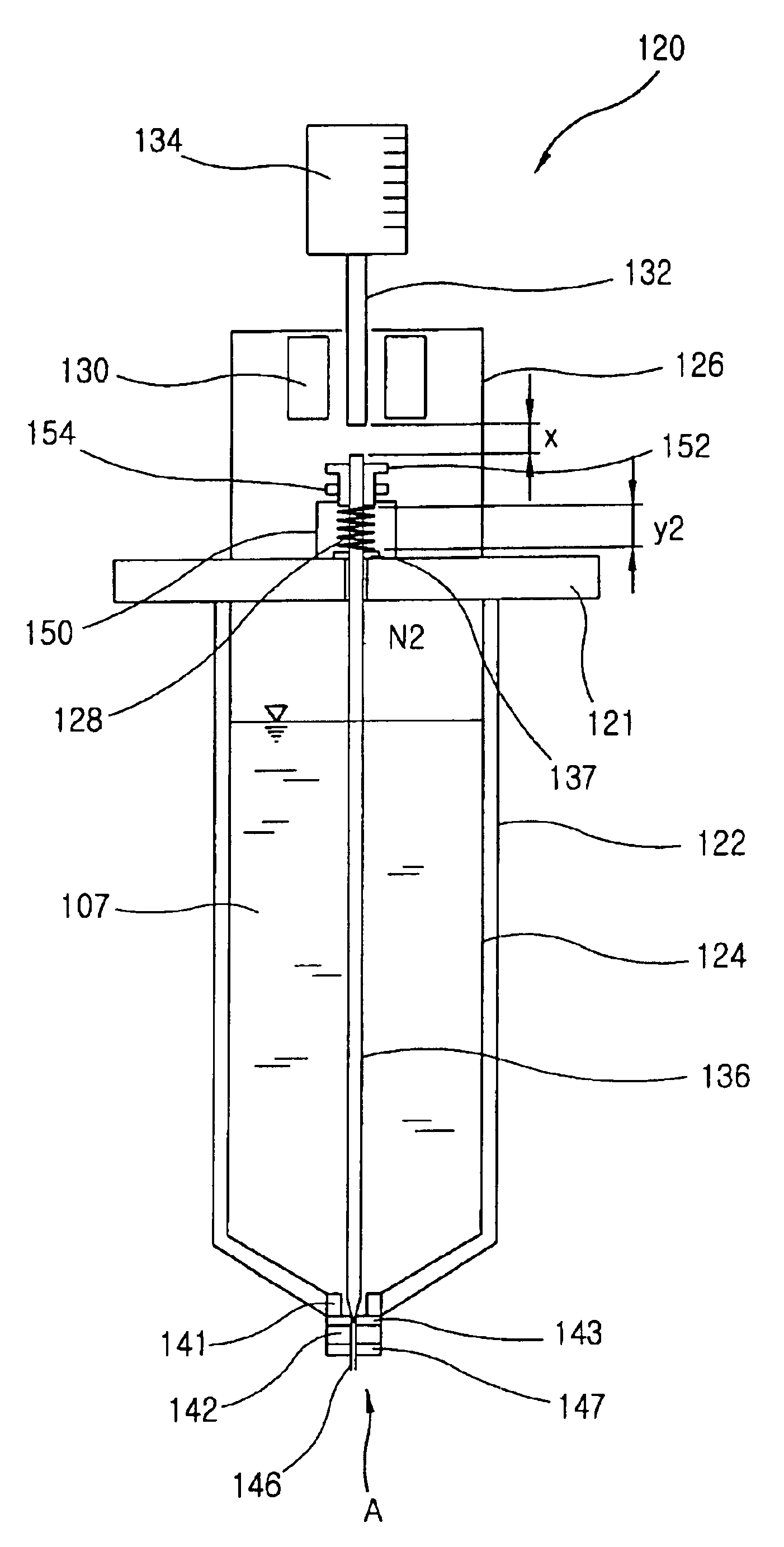
Reference will now be made in detail to an embodiment of the present invention, the example of which is shown in the accompanying drawings.

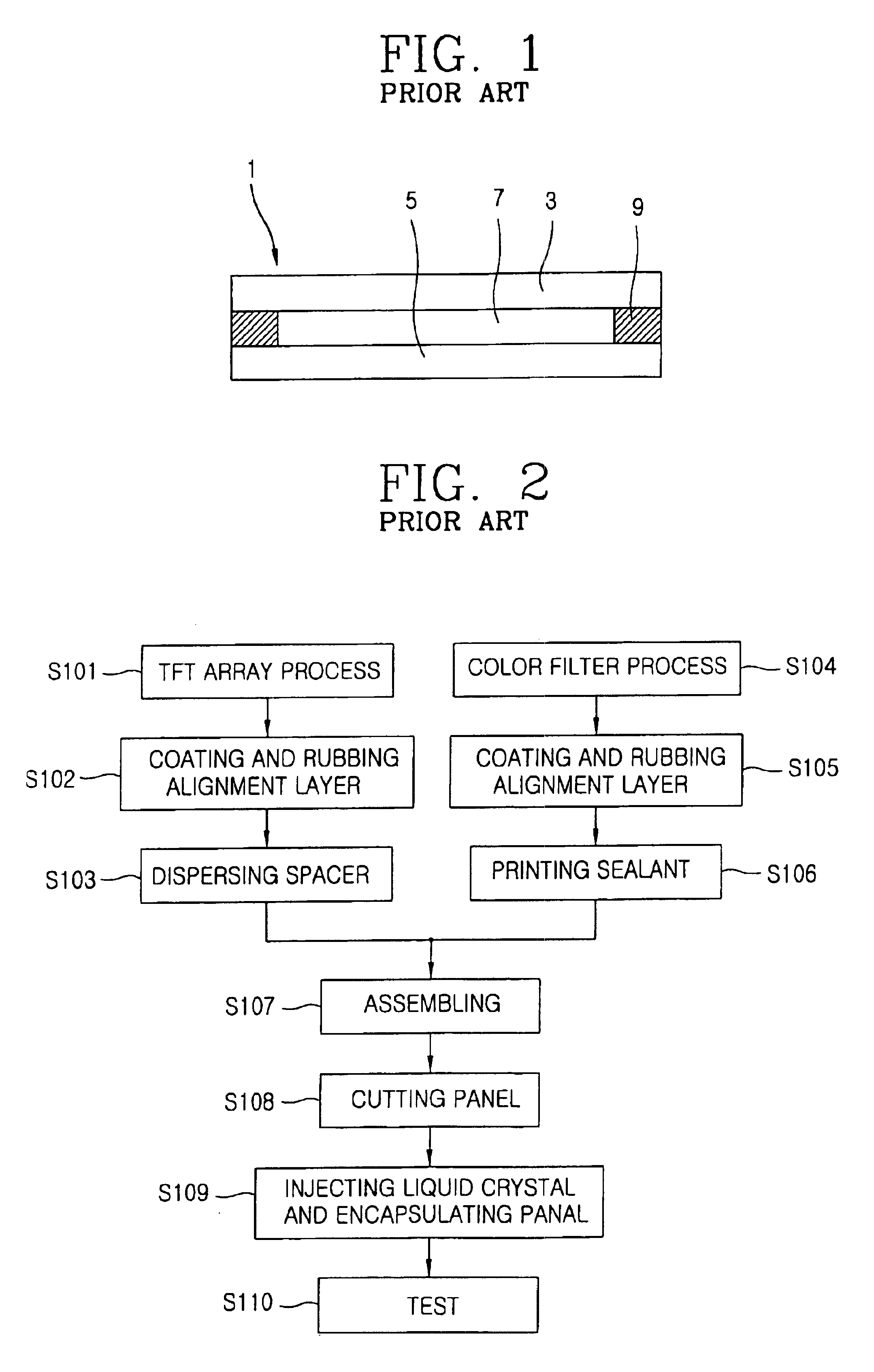
To solve the problems of the conventional liquid crystal injection methods, a novel liquid crystal dropping method has been recently introduced. The liquid crystal dropping method forms a liquid crystal layer by directly applying liquid crystal onto a substrate and then spreading the applied liquid crystal by pressing substrates together. According to the liquid crystal dropping method, the liquid crystal is applied to the substrate in a short time period such that the liquid crystal layer can be formed quickly. In addition, liquid crystal consumption can be reduced due to the direct application of the liquid crystal, thereby reducing fabrication costs.

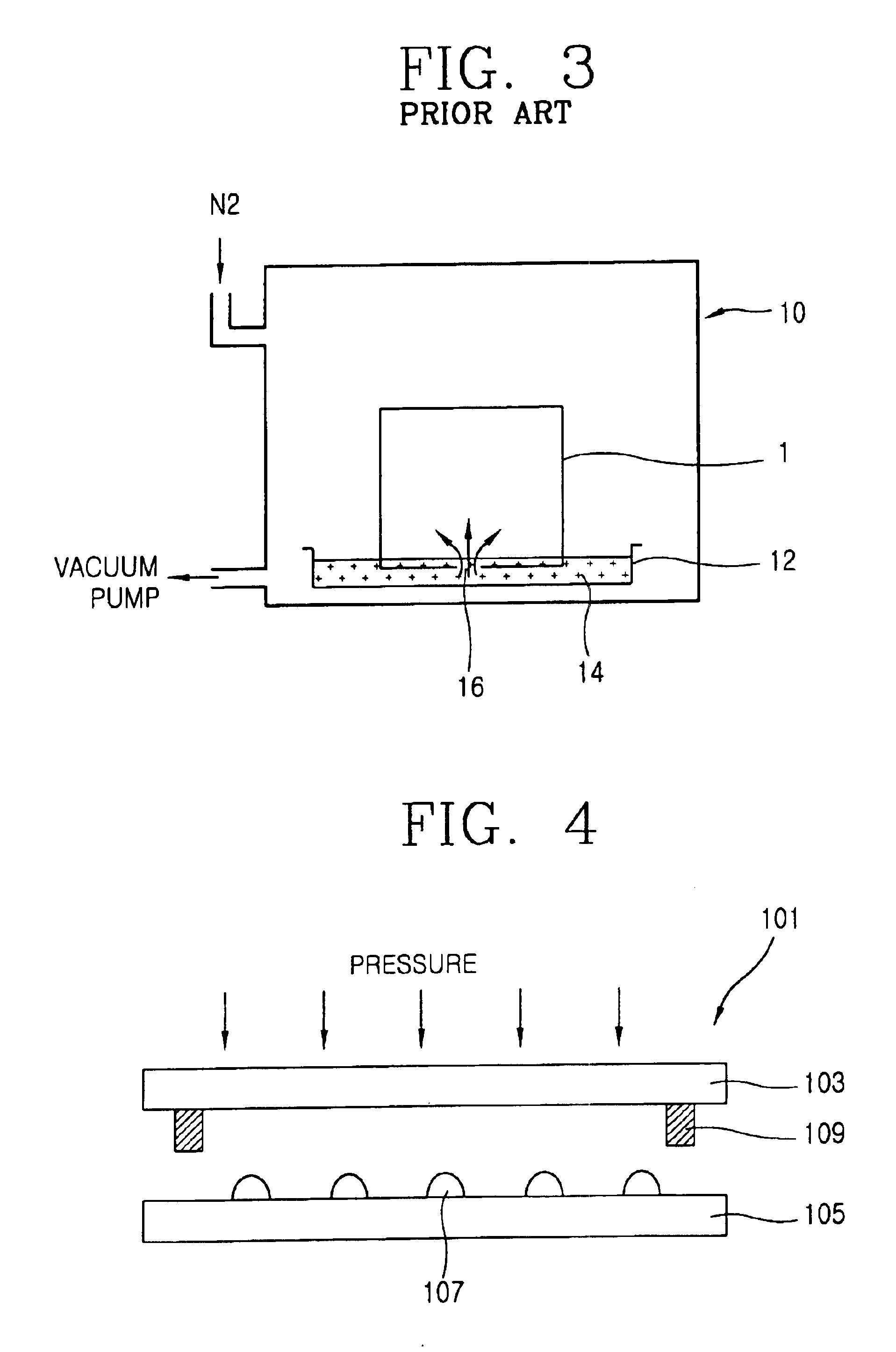
FIG. 4 illustrates the basic liquid crystal dropping method. As shown, liquid crystal is dropped (applied) directly onto a lower substrate 105 before the lower substrate 105 and the upper substrate...


PUM

PropertyMeasurementUnit
tensionaaaaaaaaaa
magnetic fieldaaaaaaaaaa
spring lengthaaaaaaaaaa

Abstract

A liquid crystal dispensing apparatus for controlling the amount of liquid crystal dropped onto a substrate by controlling the tension of a spring. The spring applies a force to a needle that forces the needle toward an opening on the end of the container so as to close the opening. A tension controller controls that length of the spring, and thus its force. A solenoid moves the needle against the spring when an electric source is applied to the solenoid such that the opening is opened. The spring tension controls the time required to return the needle to a position that closes the opening. The spring tension also controls the amount of liquid crystal that is ejected when the opening is opened.

Description

1. Field of the InventionThe present invention relates to a liquid crystal dispensing apparatus that dispenses a controlled amount of liquid crystal, with the dispensed amount depending on the tension of a spring.2. Description of the Related ArtPortable electric devices, such as mobile phones, personal digital assistants (PDA), and notebook computers, often require thin, lightweight, and efficient flat panel displays. There are various types of flat panel displays, including liquid crystal displays (LCD), plasma display panels (PDP), field emission displays (FED), and vacuum fluorescent displays (VFD). Of these, LCDs have the advantages of being widely available, easy to use, and superior image quality.The LCD displays information based on the refractive anisotropy of liquid crystal. As shown in FIG. 1, an LCD 1 comprises a lower substrate 5, an upper substrate 3, and a liquid crystal layer 7 that is disposed between the lower substrate 5 and the upper substrate 3. The lower substr...

Claims


Application Information

Patent Timeline
Patent Type & Authority Patents(United States)
IPC IPC(8): B05C5/02G02F1/1341G02F1/13
CPCB05C5/0212B05C5/0291B05C5/0225G02F1/13
Inventor KWEON, HYUG JINSON, HAE-JOON
Owner LG DISPLAY CO LTD
Why Eureka
Try Eureka