Packaging apparatus and method

a technology of packaging apparatus and method, which is applied in the direction of bundling articles, bundling machine details, packaging goods types, etc., can solve the problems of machine disadvantage, object may be able to shift around in the resulting package, and is more susceptible to being damaged, so as to control the draw-off tension of the web

Inactive Publication Date: 2005-05-24
SEALED AIR U S
View PDF39 Cites 20 Cited by
  • Summary
  • Abstract
  • Description
  • Claims
  • Application Information

AI Technical Summary

Benefits of technology

[0009]The present invention addresses the above needs and achieves other advantages. In one aspect of the invention, an apparatus for packaging an item includes a pair of rolls that form a nip through which two opposing web portions pass with the item disposed between the web portions. At least one of the rolls has a resiliently compliant roll portion in registry with the item passing through the nip. The item deforms the resiliently compliant roll portion(s) as the item passes through the nip, and the restoring force of the compliant roll portion(s) causes the web portions to be pressed against the item so as to closely conform to the item's contour. The facing surfaces of the web portions present sealing material for sealing the web portions together; various types of sealing materials can be used, cohesive being one advantageous choice because of its propensity to adhere only to itself and its ability to adhere at non-elevated temperature. The web portions are sealed together about the periphery of the item, aided by the pressing action of the compliant roll portion(s). The resiliently compliant roll portions thus act to make the web portions as flat and smooth as the contour of the packaged item will allow, which helps reduce wrinkling of the web portions. The resiliently compliant roll portions may comprise a foam such as polyurethane foam. In one embodiment a foam cover surrounds a substantially rigid core or shaft of the roll. The foam cover can be a plurality of separate cylindrical segments arranged end-to-end such that the segments are independently deformable, or can be a single continuous foam cover. To substantially center the packaged object in the thickness direction, both rolls may have the resiliently compliant roll portion.
[0011]The apparatus may include side seal devices for making side seals on either side of the packaged item and a cross seal device for making transverse cross seals ahead of and behind the item. The side seal devices may be operable to seal the web portions together at locations closely adjacent the opposite side edges of the packaged item (and spaced inwardly from the longitudinal edges of the web portions) regardless of the width of the item in relation to that of the web portions. In one embodiment, the side seal devices are operable to move transversely inward from the opposite longitudinal edges of the web portions toward the item being packaged until the side seal devices are at locations closely adjacent but spaced from opposite sides of the item. The side seal devices then seal the web portions together, whereby the item is prevented from shifting transversely toward either longitudinal edge of the web portions. This improves the edge or corner protection provided by the package.
[0012]The side seal devices in one embodiment comprise pairs of roller balls forming nips. One pair of balls is mounted on a carrier at one longitudinal edge of the web portions such that the web portions pass through the nip between the two balls; the other pair of balls is similarly disposed at the other longitudinal edge of the web portions. The carriers are driven inwardly and outwardly in the transverse direction by a traversing mechanism. The traversing mechanism is controlled to drive the side seal devices inwardly toward the packaged item as the web portions are advanced, thus pressing and sealing the web portions together. The inward advancement of the side seal devices is halted when the side seal devices are closely adjacent to but spaced from the side edges of the item.
[0013]In one embodiment of the invention, the proximity of the side seal devices to the item is determined based on the level of current supplied to an electric drive motor of the traversing mechanism. The current required to drive the motor increases as the side seal devices closely approach the item, and the advancement of the devices is halted when the current exceeds a threshold level. Alternatively or additionally, the advancement can be halted based on a detected transverse position of the side seal devices in relation to a predetermined width of the item. The side seal devices are retracted back toward the longitudinal side edges of the web portions as the web portions with the item therebetween continue to be advanced. Accordingly, an arcuate or hourglass-shaped side seal is formed on each side of the item, with the inward portion of the seal being close to the item. The item is thereby prevented from shifting transversely within the package to any significant extent.
[0018]The apparatus may include a quick-change mounting system for mounting supply rolls of web material. The quick-change mounting system includes a core shaft configured to be inserted into and engage a core of a supply roll such that the supply roll is constrained to rotate with the core shaft. An end of the core shaft has a brake wheel mounted thereon for rotation with the shaft. The system includes a receptacle for receiving and rotatably supporting the brake wheel and has a brake shoe that is urged against the brake wheel by a clamp so as to resist rotation of the supply roll and thereby control draw-off tension of the web. The clamp includes a quick-release latch. The clamp is adjustable to adjust the clamping force and hence the draw-off tension, and the latch can be opened and closed without changing the adjustment. Thus, a new supply roll can be installed without having to readjust the draw-off tension setting.

Problems solved by technology

One problem with such machines is that if the object to be packaged is considerably narrower than the space between the longitudinal seal devices, the object may be able to shift around within the resulting package.
This is undesirable in many cases; for example, the object may be able to shift into a position close to one corner of the package and thus be more susceptible to being damaged if the package is dropped on the corner.
Thus, such machines have disadvantages when it comes to packaging a variety of objects of different sizes and / or different shapes.
With conventional machines, another problem that frequently arises is that the packaged object is not centered between the two web portions in the thickness direction of the object, i.e., in a direction normal to the surfaces of the web portions.
If the object is offset in the thickness direction toward one web portion, the frequent result is that the overlying longitudinal edges of the web portions are not properly aligned with each other; the edge (or both edges in the case of a dual-web machine) of the web portion toward which the object is offset tends to be pulled transversely inward toward the longitudinal centerline of the web portion because the web portion must curve outward to a greater extent than the other web portion.
This results in package edges that are unsightly.
Another problem with many types of flexible packaging machines of the above-noted type is that the web materials tend to become wrinkled as a result of being forced to bend and curve by the contour of the object being packaged.
In some cases, no attempt is made to eliminate the wrinkling, and the result is that packages are made that are not very aesthetically pleasing.
The problem tends to become worse as the height or thickness of the packaged object increases, since the web material is forced to curve and bend to a greater extent.
Therefore, the conventional machines are not well suited to packaging a variety of objects of different thicknesses, sizes, and shapes, since a machine set-up that may minimize wrinkling for one object configuration and / or one type of web material may not work well for a different object configuration and / or different web material.
This approach, however, is unappealing because it complicates the design of the machine, and changing the machine set-up wastes time that could better be used producing packages.
Furthermore, if the range and number of object configurations are substantial, it might be necessary to switch between several different widths of the same web material, which would be cumbersome, particularly if object configurations were changed frequently.

Method used


Image

  • Packaging apparatus and method
  • Packaging apparatus and method
  • Packaging apparatus and method

Examples


Embodiment Construction

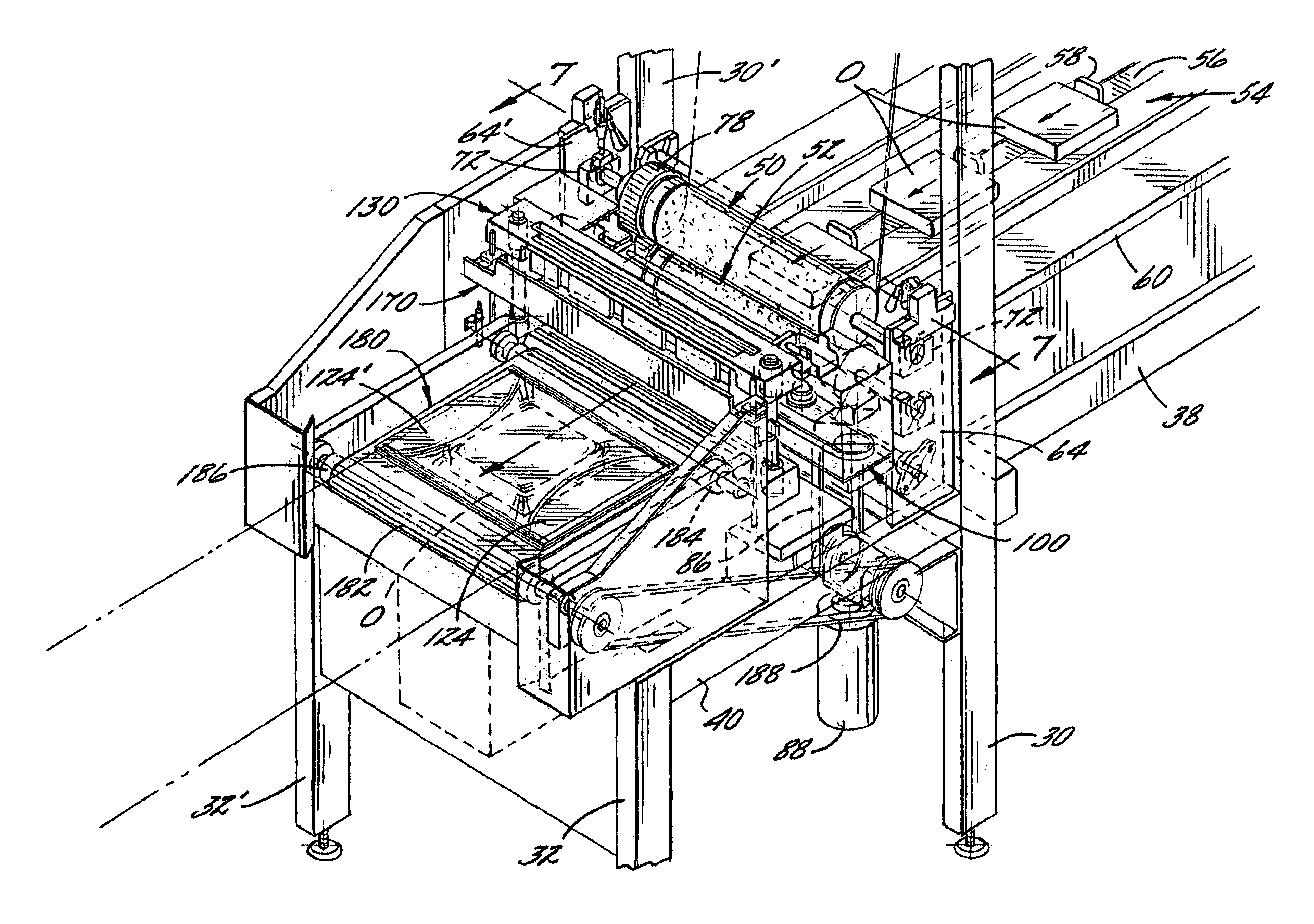
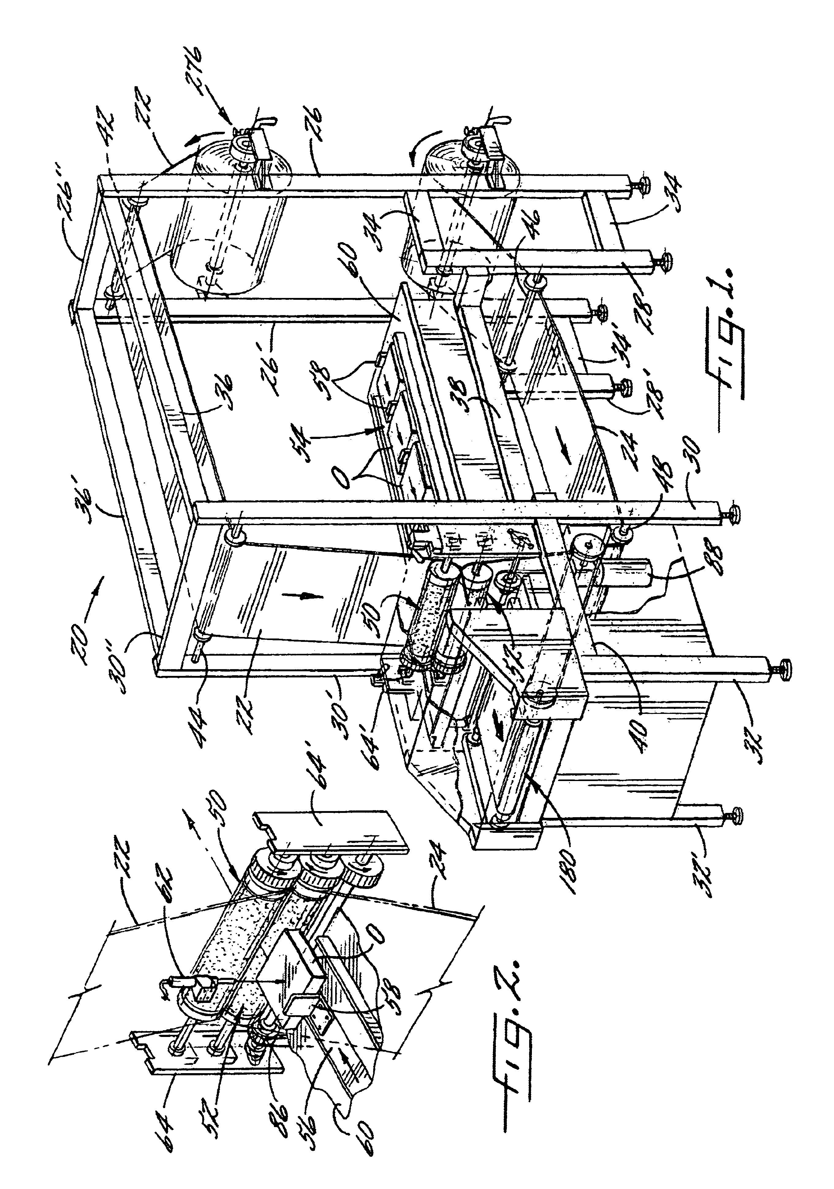
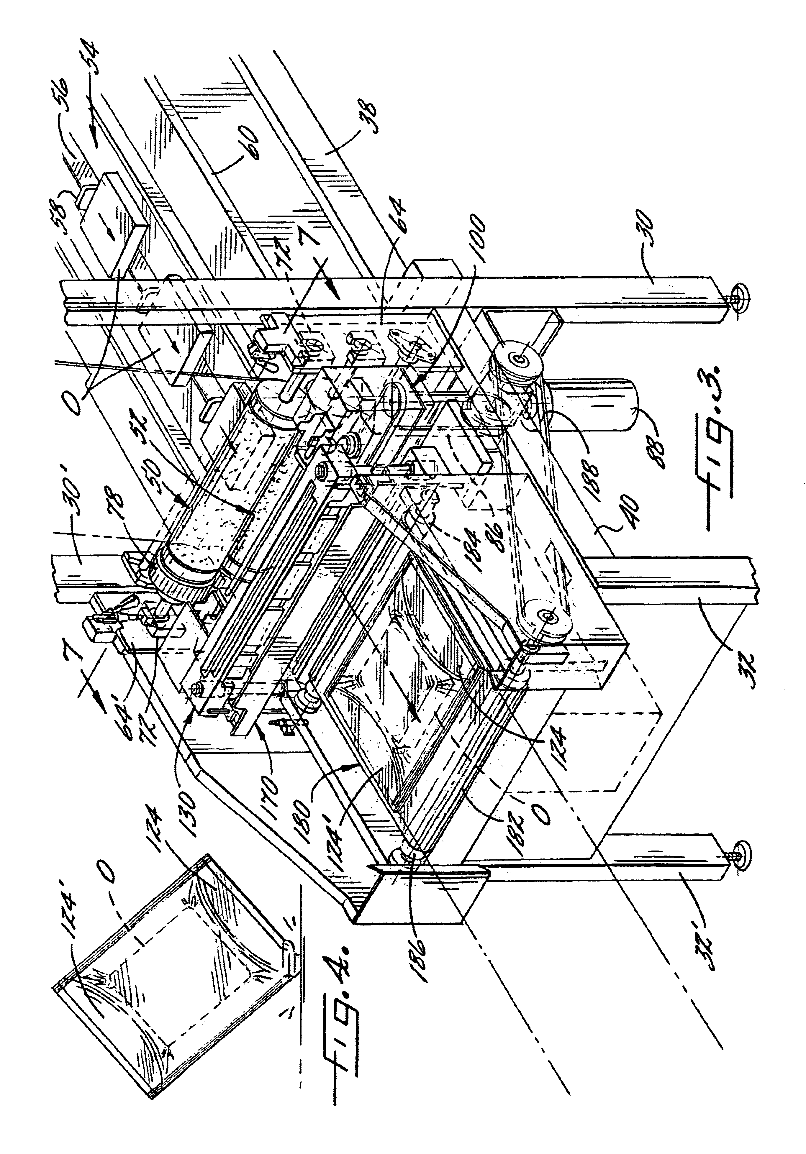
[0039]The present inventions now will be described more fully hereinafter with reference to the accompanying drawings, in which some but not all embodiments of the invention are shown. Indeed, these inventions may be embodied in many different forms and should not be construed as limited to the embodiments set forth herein; rather, these embodiments are provided so that this disclosure will satisfy applicable legal requirements. Like numbers refer to like elements throughout. Throughout the specification, where there are two of the same reference numbers one of which has a prime designation, the unprimed reference number refers to a component on the left side of the longitudinal centerline of the apparatus and the primed reference number refers to a corresponding component on the right side of the longitudinal centerline, as viewed in the downstream direction.

[0040]A packaging apparatus 20 in accordance with one embodiment of the invention is shown in FIG. 1. The apparatus 20 is of ...


PUM

PropertyMeasurementUnit
densityaaaaaaaaaa
flexibleaaaaaaaaaa
pressureaaaaaaaaaa

Abstract

A packaging apparatus includes a pair of rolls forming a nip through which two web portions are passed with an item to be packaged between the web portions. The rolls include resiliently compliant roll portions that deform to accommodate the thickness of the item, and the roll portions press the web portions to seal them together in peripheral regions surrounding the item and to center the item between the webs in the thickness direction. The apparatus also includes side seal devices that traverse inwardly toward the item to seal the webs together close to the item's opposite side edges to prevent the item from laterally shifting. The web portions may have cohesive disposed on their facing surfaces such that the web portions adhere to each other with pressure but tend not to adhere to the packaged item or other surfaces.

Description

FIELD OF THE INVENTION[0001]The present invention relates to machines and methods for packaging items using flexible or semi-flexible sheet materials in continuous web form, wherein an object is disposed between two portions of sheet material and the two portions are sealed together about the periphery of the object to form a package that is then severed from the remainder of the web material.BACKGROUND OF THE INVENTION[0002]Flexible packaging has long been used to package products such as books, compact discs, cassette tapes, and a host of other types of items to provide protection when shipping or mailing the items, and in some cases to hermetically seal the objects from the outside environment. Web-handling machines have been developed to automate the process of packaging objects in flexible packaging materials. Dual-web machines bring a pair of webs into generally parallel confronting relation with each other and feed a product, or a group of products, between the webs. Longitud...

Claims


Application Information

Patent Timeline
Patent Type & Authority Patents(United States)
IPC IPC(8): B65B9/00B65B49/06B65B49/00B65B9/02B65B51/10B65B51/12
CPCB65B9/026B65B51/12B65B49/06
Inventor SPERRY, LAURENCE B.DAVLIN, ANTHONY O.KANE, ERIC A.DRAKE, JESSE S.
Owner SEALED AIR U S
Why Eureka
Try Eureka