Surface-mount type antenna and antenna apparatus

a surface-mount type, antenna technology, applied in the structure of elongated active elements, resonant antennas, radiating electrodes, etc., can solve the problems of increasing the dielectric constant of the base, abruptly changing the antenna characteristics to narrow-band characteristics, and slimming of the radiating electrod

Inactive Publication Date: 2004-10-19
KYOCERA CORP
View PDF4 Cites 17 Cited by
  • Summary
  • Abstract
  • Description
  • Claims
  • Application Information

AI Technical Summary

Benefits of technology

According to the invention, the radiating electrode is disposed helically across the surfaces of the base body in such a way that it extends from the one side surface, across the one principal surface, the other side surface, and the other principal surface, and then returns to the one side surface and further extends, through the one principal surface, toward the one end of the one side surface, and further the other feeding-terminal-side end of the radiating electrode extends across the surfaces of the base body, i.e., extends from the one principal surface, through the other side surface, toward the other principal surface, so as to form the wide-area portion facing the feeding terminal. With this configuration, the radiating electrode can be made longer, and also the wide-area portion of the radiating electrode can be electro magnetically coupled to the feeding terminal through an electric capacitance generated therebetween. Moreover, at the time of mounting on the mounting substrate, since a large capacitance can be created between the wide-area portion of the radiating electrode and the ground conductor layer of the mounting substrate, the resonant frequency of the radiating electrode can be decreased. This makes it possible to achieve miniaturization of the antenna without increasing the dielectric constant of the base body and without excessively slenderizing the radiating electrode.
As described heretofore, according to the invention, it is possible to provide a surface-mount type antenna and an antenna apparatus capable of attaining satisfactory antenna characteristics with stability, of enhancing radiation efficiency, and of achieving miniaturization.

Problems solved by technology

However, an increase in the dielectric constant of the base body 51 gives rise to a problem of the antenna characteristics being abruptly changed to narrow-band characteristics.
On the other hand, slimming of the radiating electrode 54 gives rise to a problem of great radiation loss.
This makes it difficult to attain the desired antenna characteristics as designed.
As a result, the center frequency of the antenna is undesirably varied.
This makes it difficult to meet the demand of the market for antenna miniaturization.
As a result, the antenna fails to provide satisfactory antenna characteristics.

Method used


Image

  • Surface-mount type antenna and antenna apparatus
  • Surface-mount type antenna and antenna apparatus
  • Surface-mount type antenna and antenna apparatus

Examples


first embodiment

Next, a description will be given as to an example of the surface-mount type antenna and the antenna apparatus of the first embodiment according to the invention. The example is built as a 1.575 GHz-band antenna designed for GPS. In the case of using an ordinary quarter-wavelength monopole antenna, the size of the antenna element is adjusted to be approximately 47 mm in length.

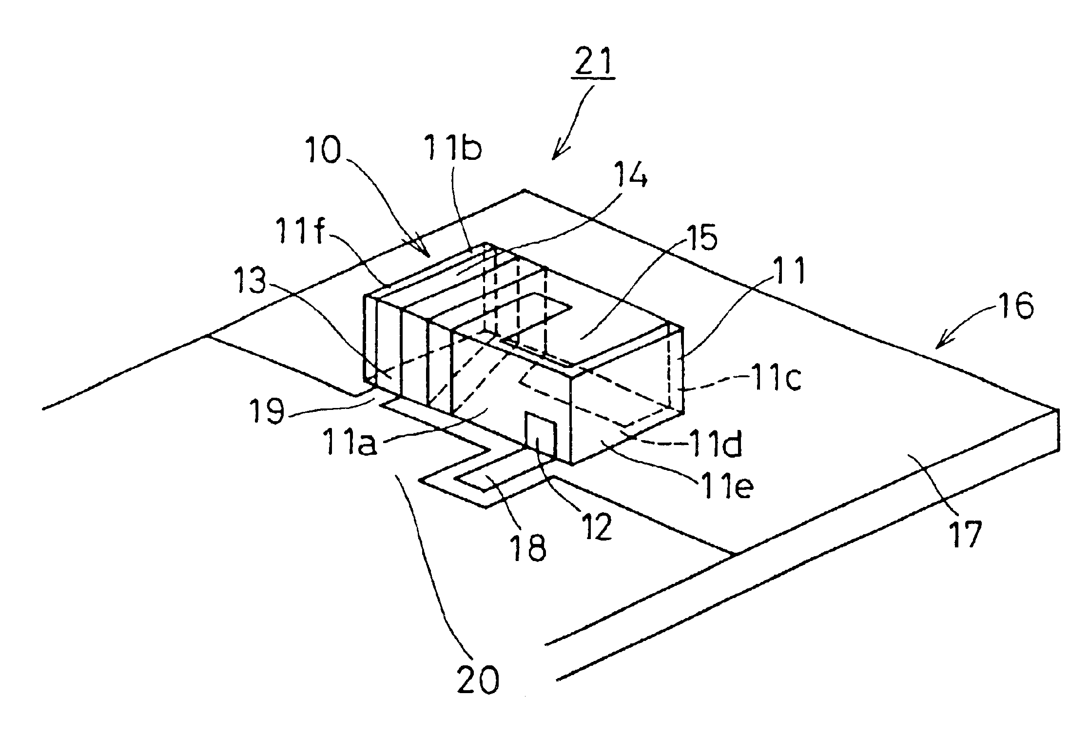
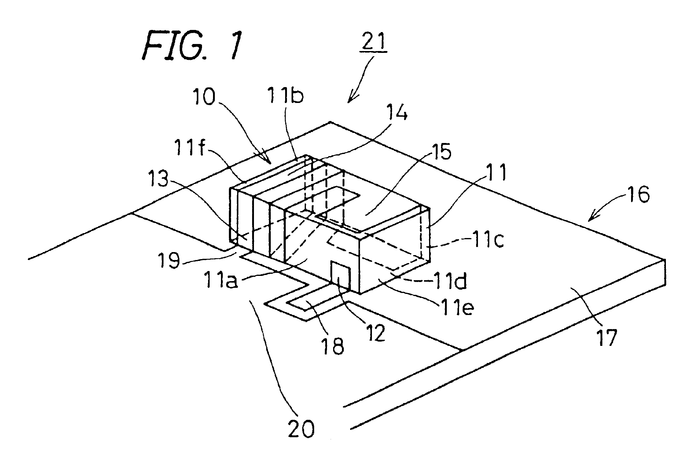
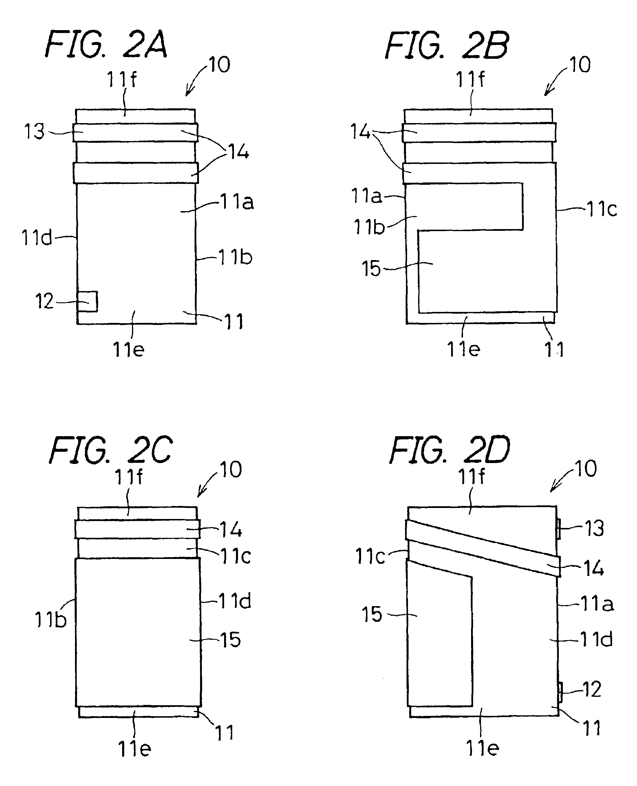
In the construction of the surface-mount type antenna 10 of the first embodiment of the invention shown in FIG. 1, there is prepared a base body 11 made of alumina ceramics (dimension: 10 mm.times.4 mm.times.3 mm). Then, using a silver conductor, a 1 mm-wide conductor pattern of helical conformation is formed. The conductor pattern, like the radiating electrode 14 shown in FIG. 1, has its one end formed into a wide-area portion 15.

As the mounting substrate 16, a 0.8 mm-thick glass epoxy substrate is used. The ground conductor layer 20 has the size of 40 mm.times.80 mm.

The surface-mount type antenna 10 is mount...

second embodiment

In a similar manner, the antenna apparatus 41 of the invention as shown in FIG. 4 is fabricated. The antenna apparatus 41 is also characterized by the center frequency of 1.575 GHz and the bandwidth of 30 MHz.


PUM


Abstract

In a surface-mount type antenna, a substantially-rectangular solid base body has a feeding terminal and a ground terminal formed on its one side surface. A radiating electrode has its one end connected to the ground terminal and is disposed helically across the surfaces of base body extending from one side surface to one principal surface. Another end of radiating electrode extends from one principal surface, through another side surface, toward another principal surface, to form a wide-area portion facing the feeding terminal. An antenna apparatus is constructed by mounting the surface-mount type antenna on a mounting substrate having formed thereon a feeding electrode, a ground electrode, and a ground conductor layer, and simultaneously connecting the feeding terminal and the ground terminal to the feeding electrode and the ground electrode, respectively.

Description

1. Field of the InventionThe present invention relates to a compact surface-mount type antenna and an antenna apparatus for use in mobile communication equipment such as a cellular phone.2. Description of the Related ArtIn keeping with rapid advancement of down-sized mobile communication equipment such as a cellular phone, miniaturization has been underway in an antenna which constitutes such equipment. Thus, for example, a surface-mount type antenna has hitherto been developed. Now, a conventional surface-mount type antenna and an antenna apparatus incorporating it will be described with reference to a perspective view shown in FIG. 8.In FIG. 8, reference numeral 50 denotes a surface-mount type antenna. This surface-mount type antenna 50 is mounted on a mounting substrate 56, thus constituting an antenna apparatus 61. In the surface-mount type antenna 50 shown in FIG. 8, reference numeral 51 denotes a substantially prismatic base body; reference numeral 52 denotes a feeding termina...

Claims


Application Information

Patent Timeline
Patent Type & Authority Patents(United States)
IPC IPC(8): H01Q1/38H01Q1/24H01Q1/36H01Q9/40H01Q9/42
CPCH01Q1/38H01Q1/243
Inventor SATO, AKINORIIKUTA, TAKANORIWATADA, KAZUOMURAKAWA, SHUNICHI
Owner KYOCERA CORP
Why Eureka
Try Eureka