Vertical take-off and landing vehicles

a technology of vertical landing and landing vehicle, which is applied in the direction of efficient propulsion technology, vertical landing/take-off aircraft, aircraft navigation control, etc., can solve the problems of engine producing extra thrust, wing generating negative lift, and aircraft control causing problems

Inactive Publication Date: 2004-10-26
MOLLER INT
View PDF4 Cites 76 Cited by
  • Summary
  • Abstract
  • Description
  • Claims
  • Application Information

AI Technical Summary

Problems solved by technology

The propeller wash affects the aerodynamic forces and moments of the aircraft causing profound difficulties in aircraft control.
In addition, at the transitional stages, the wing can generate negative lift due to the propeller wash and the engine must produce extra thrust to compensate for the negative lift.
Also, a large aerodynamic drag is generated on the wings during hovering and reduces payload.
This approach is user unfriendly with large rotating open blades.
In addition, in a case like the V22 Osprey, the aircraft cannot land conventionally with the rotors transitioned to the forward flight position because the rotors are so large that they would contact the ground.
Another disadvantage of this approach is that the rotors of the aircraft must be geared together by a gearbox to prevent catastrophic failure should an engine fail, and gearbox failure is the major mechanical failure mode in the aircraft.
However, ducts that rotate through the full 90 degrees can create leading edge stall at some point in the transition where the duct is still at a high angle and the aircraft is flying quite fast.
If this airflow stall occurs, a successful transition is unlikely.
Many VTOL aircraft employing this approach have crashed.
The fixed camber vane system can only direct a limited amount of airflow through very modest angles before the flow separates creating thrust loss.
The inventor has found a disadvantage in this design, however.
The problem with doing this is that the cross-sectional area of the flow as it moves through the vanes changes dramatically, as shown in FIG. 1A of this application.
Upon further turning of the flow stream, the boundary layer thickness can grow to a considerable size, which can lead to flow separation and, as a consequence, reduce the effective cross-sectional area of the airflow and lower the efficiency of the vanes.
In this case, the flow speeds up and slows down for no useful purpose with an associated pressure thrust loss.
Another drawback of this solution is the development of a boundary layer near the trailing edge of the vanes, which will reduce the efficiency of the vane system.
As mentioned above, various aerodynamic and control problems of the first approach occur at the transitional stages.
Also, the existing tilt-rotors have inherent complexities in the design of propellers themselves and structural mechanism for propeller cyclic pitch control.
In the second approach, the efficiency of the vane systems declines as the flow turning angle increases.

Method used


Image

  • Vertical take-off and landing vehicles
  • Vertical take-off and landing vehicles
  • Vertical take-off and landing vehicles

Examples


embodiment 100

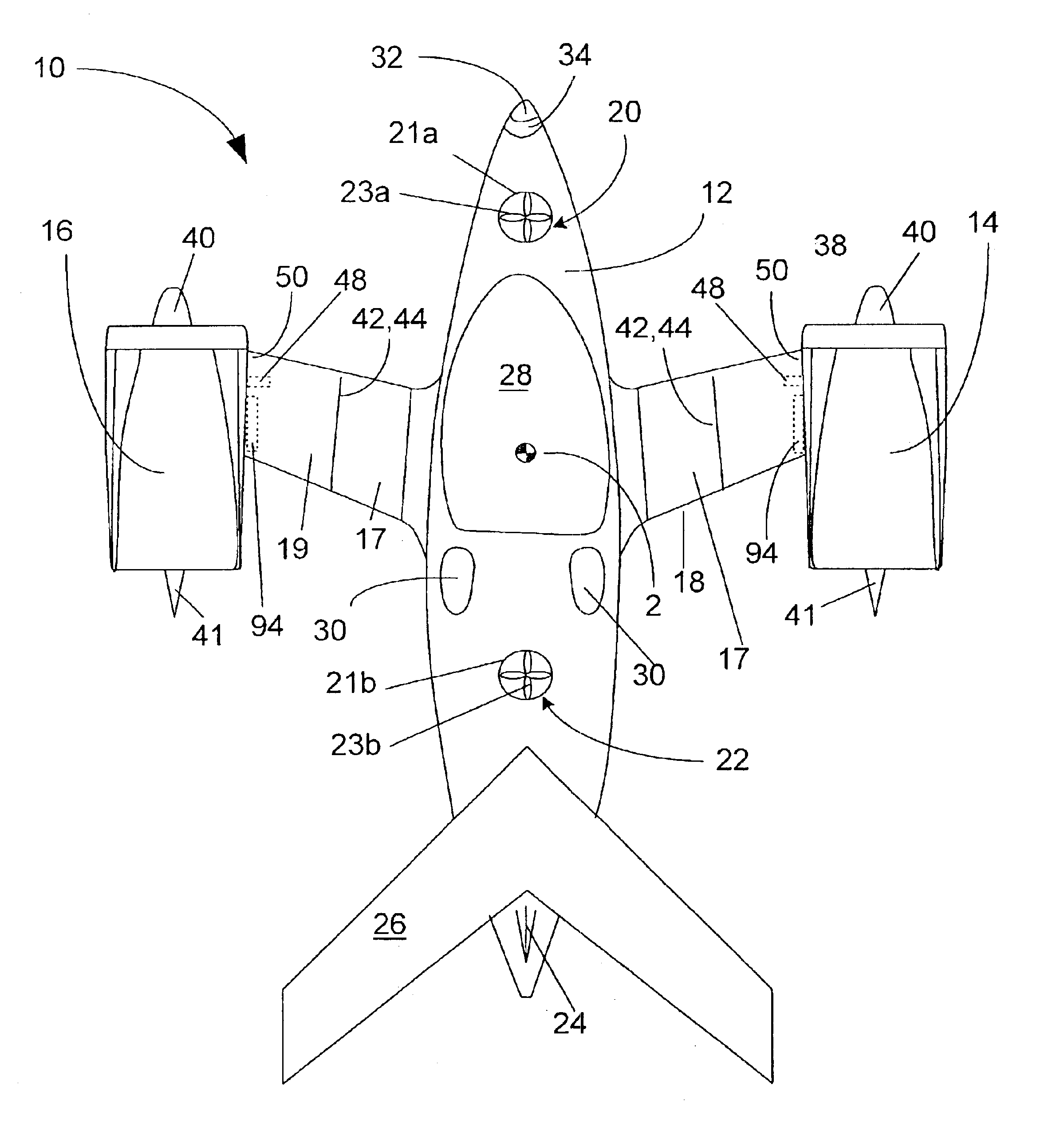
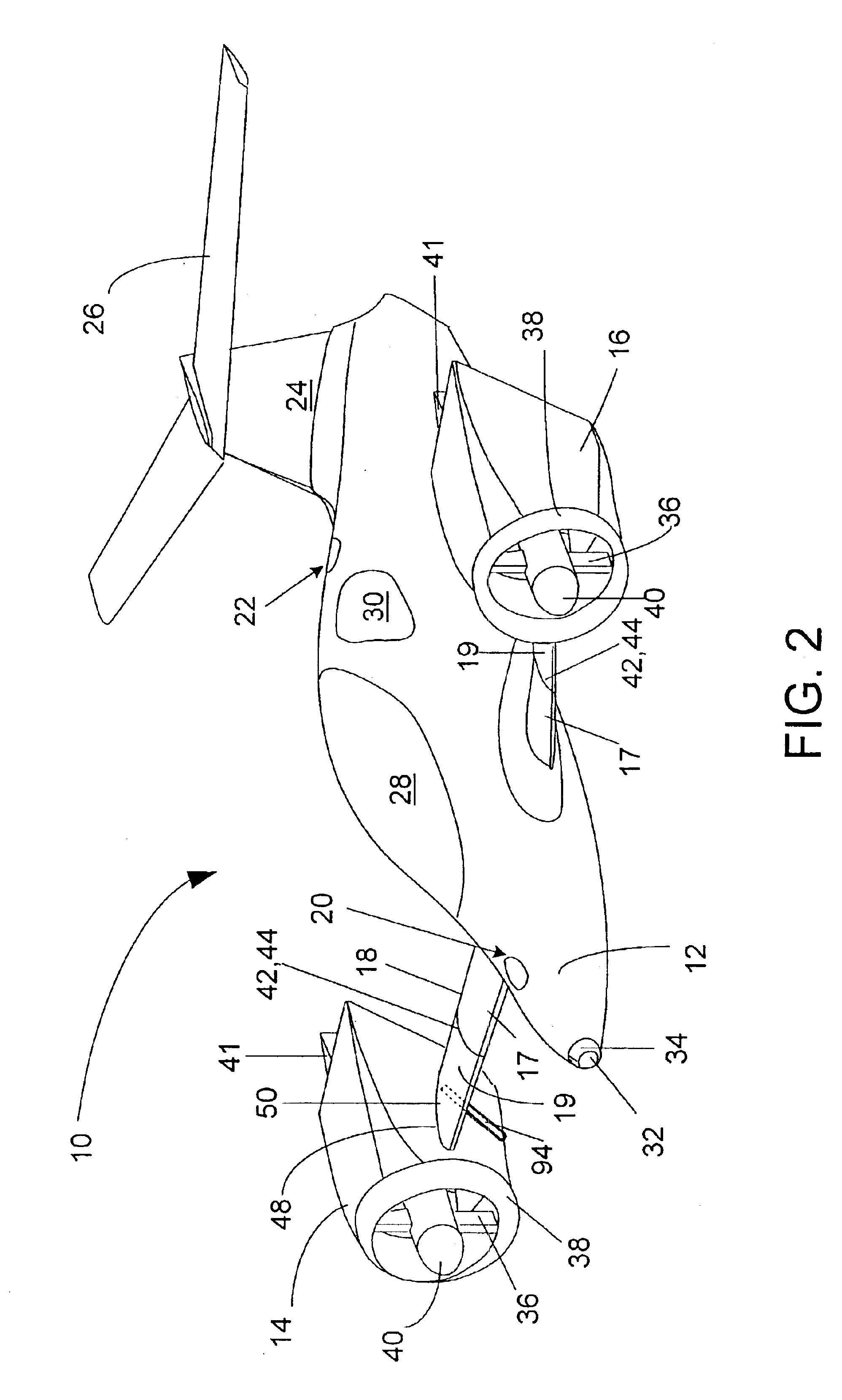
An alternate embodiment 100 is shown in FIGS. 16-19. As illustrated in FIG. 16, the alternate embodiment has most of the components of the first embodiment; a fuselage 112, a pair of wings 118 foldable at break lines 119, a vertical stabilizer 124, a horizontal stabilizer 126, a transparent canopy 128, two passenger windows 130, and a first pair of nacelles 114 and 116 rotatively attached to the wingtips 150 and rotatable by linear actuators 152. However in this embodiment, embodiment 100, two additional nacelles 115 and 117 are also rotatively attached to the fuselage 112 by short wings 155 and are rotatable by additional pair of linear actuators (not shown).

In this embodiment, the wings 118 and the rear nacelles 114 and 116 have been moved further towards the rear of the fuselage 112 as compared to the first embodiment, and the forward pair of nacelles are attached to fuselage 112 forward of the canopy 128. All four nacelles 114-117 can rotate to approximately 45 degrees from the ...


PUM


Abstract

A VTOL vehicle including a fuselage with two foldable wings, two tiltable nacelles attached to the wings, a vertical stabilizer, a horizontal stabilizer, and two auxiliary thrusters. Each nacelle contains a system of vanes located at the rear opening thereof, and actuators are provided for extending and retracting the vanes in conjunction with nacelle tilting mechanisms to deflect the airflow over a predetermined range of angles from the horizontal. Each nacelle also contains two rotary engines, each of which directly drives a fan. The fans face each other and operate in counter-rotating directions at the same rotational speed. An alternative embodiment includes two additional nacelles attached to the fuselage instead of having the auxiliary thrusters. A redundant computerized flight control system maintains stability of the vehicle as it transitions from one flight mode to another.

Description

1. Field of the InventionThe present invention relates generally to VTOL vehicles, and more particularly to an improved VTOL vehicle having ducted fan propulsion systems wherein nacelles forming ducts housing the engines can be tilted, and the thrust can be selectively vectored by tilting the nacelles and actuating adjustable vanes mounted in the aft portion of each nacelle duct.2. Brief Description of the Prior ArtSeveral attempts have been made to create a vehicle that can be flown in the air as well as driven on land. It is desirable that such craft be capable of vertical takeoff / landing (VTOL) in order to minimize the runway space necessary for lift-off. One approach to achieve required lift for take-off / landing and thrust for conventional level flight includes the tilting of engine driven fans or propellers to vector the thrust from the vertical to the horizontal direction. Another approach mounts fans in a fixed position and various means providing for deflecting the flow gene...

Claims


Application Information

Patent Timeline
Patent Type & Authority Patents(United States)
IPC IPC(8): B64C11/00B64C13/00B64C11/48B64C13/50B64D27/06B64C29/00B64C3/00B64C3/56B64D27/00B64D31/00B64D31/06B64C37/00
CPCB64C3/56B64C11/001B64C11/48B64C13/503B64C37/00B64D27/06B64D31/06B64C29/0033Y02T50/145Y02T50/10
Inventor MOLLER, PAUL S.
Owner MOLLER INT
Why Eureka
Try Eureka