Fastening device for screening panels

a technology of fastening device and screening panel, which is applied in the direction of sieving, sheet joining, solid separation, etc., can solve the problems of failure after a period, and achieve the effect of enhancing security and minimising effective siz

Inactive Publication Date: 2004-11-02
OWEN DAVID LLEWELLEN
View PDF12 Cites 6 Cited by
  • Summary
  • Abstract
  • Description
  • Claims
  • Application Information

AI Technical Summary

Benefits of technology

In accordance with a preferred embodiment of the invention, the fastener is provided in combination with a toggle or butterfly near an end of the metal tensile component, for engaging a blind hole in a screening frame. A blind hole may arise where the frame uses, for example, square tube members, or other structural members where the tensile member must be connected without access to both sides of the member. The toggle may comprise a strip or plate with the tensile member passing through an offset hole, the plate narrow enough to be passed through a hole in the screening frame member when misaligned, but long enough to be held when aligned. The hole in the screening panel must be of larger diameter than would be necessary for the shaft of the tensile member, e.g. a bolt, to pass through in normal manner. This enlarged hole is large enough to allow the tensile member and toggle to pass through, suitable angled to minimise their effective size. Preferably the polymeric holding component is provided with a further step which fits into the enlarged hole provided in the screen frame, thus locating the tensile member and toggle in a holding position with enhanced security.

Problems solved by technology

If the area is too small, the shearing stresses in the panel material rise to levels at which localised heating develops and the molecular structure of the polymer tends to degrade, leading to failure after a period.

Method used


Image

  • Fastening device for screening panels
  • Fastening device for screening panels
  • Fastening device for screening panels

Examples


Embodiment Construction

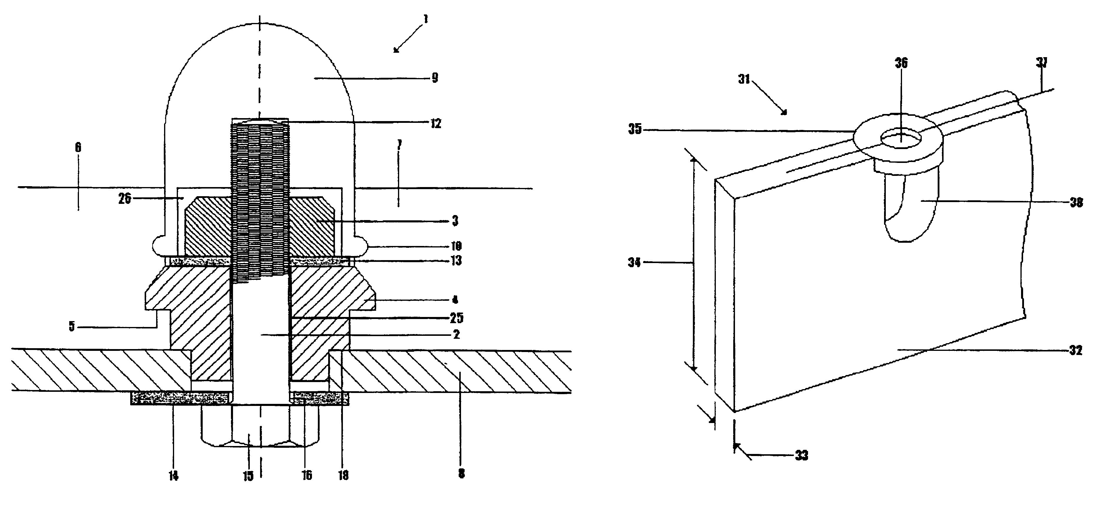
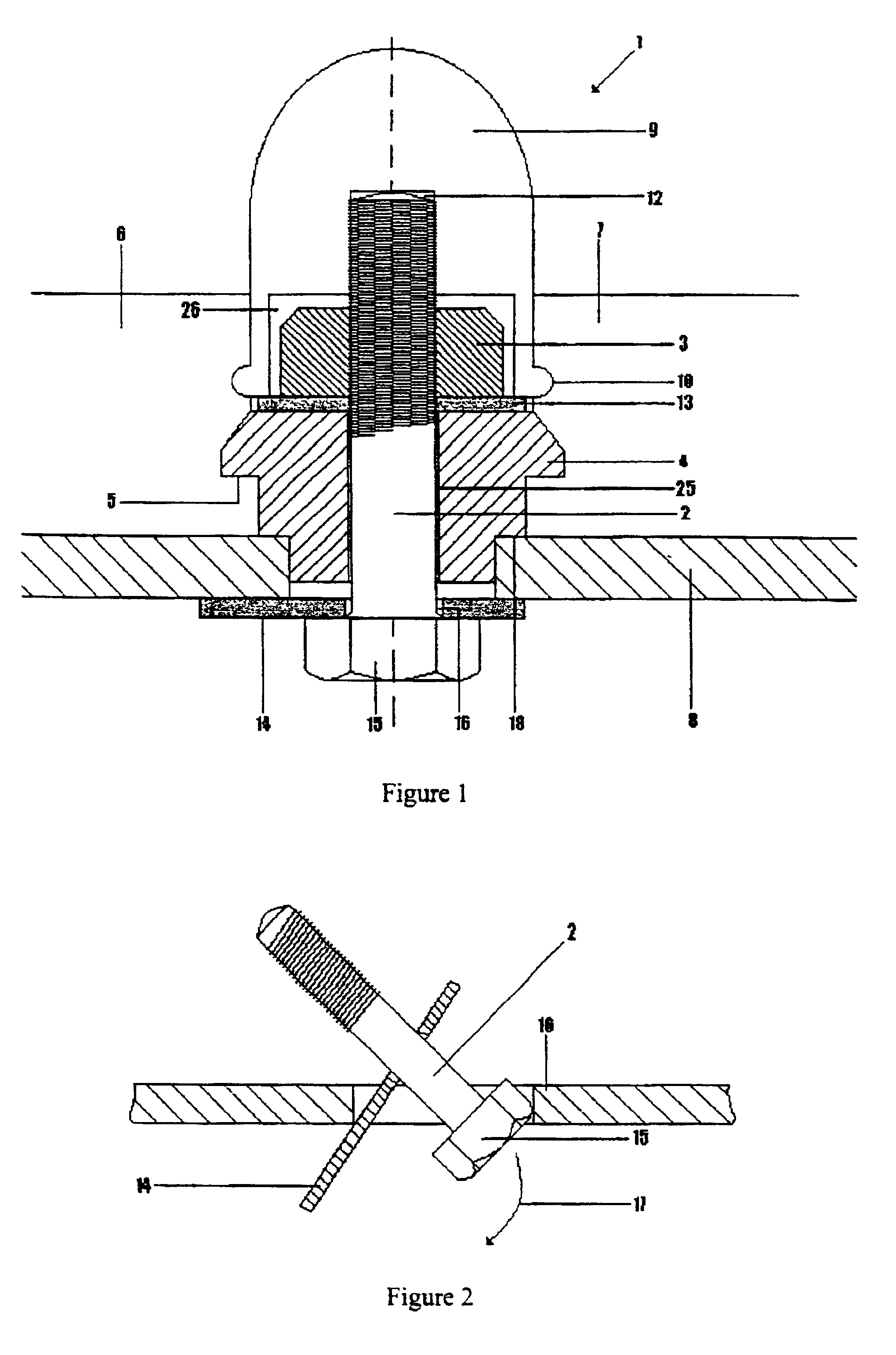
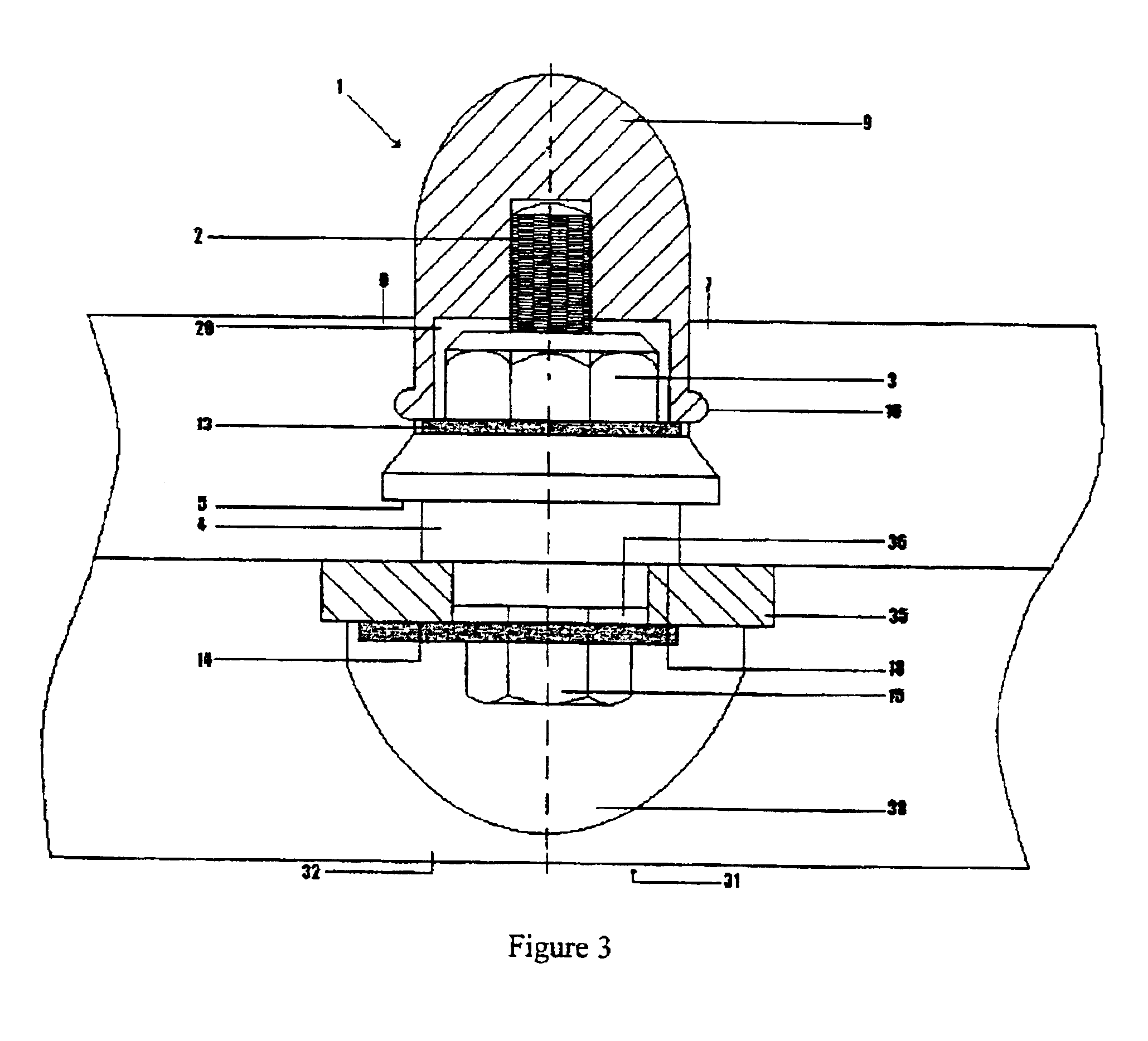
As shown in FIG. 1, the fastener 1 comprises a combination structure of a metal (steel) tensile component, in the form of a bolt 2 and nut 3, and a polymeric (polyurethane) holding component 4. The holding component 4 has a ledge 5 or shoulder for holding contiguous panels 6 and 7 and a hole 26 for the bolt. The ledge is formed by a step down in diameter of the bush-like shape of the holding component. The fastener fastens the panels 6 and 7 to a screen frame B. The upper end of the bolt and the nut are covered by a cover 9, also of polyurethane. The cover has a skirt 10 which fits into a co-acting recess formation 11 (see FIG. 7) in the edges of the panels. The bore 12 of the cover is a tight or force fit onto the thread of the bolt, the cover can be knocked on with a hammer. An enlarged part 26 of the bore accomodates the nut 3. A lock washer 13 is used under the nut. A toggle 14 is provided under the bolt head 15 with the bolt passing through an off centre hole 16 in the toggle. ...


PUM


Abstract

A fastening device (1) for fastening polyurethane screening panels (6,7) to a screen (8) is made up of a composite fastener and a disc stringer support. The composite fastener is a steel bolt (2) and nut (3) with a polyurethan holding component (4) and a polyurethane cover (9) for the bolt head. The disc and stringer support is a stringer (31) serving as a joist spanning between girders of the screen frame, the stringer (31) having no flange and being narrow and deep, with discs (35) set in the top surface of the stringer at spaced apart positions, having a hole (36) in each disc for the bolt and nut and a recess (38) in the stringer underneath each disc for the nut. The bolt and nut have a toggle (14) which allows insertion into the hole in the disc and tightening the bolt and nut entirely from above the screen.

Description

This invention lies in the field of screening particulate material, non-limiting examples are screens which are used extensively in grading of ores and other materials in mining and process operations. In addition to woven wire screens and perforated sheet and plate screens, screens made up of a plurality of screening panels have attained wide application. Such screening panels, for example, are manufactured by casting a suitable grade of polyurethane and the panels are mounted contiguously in a tiling fashion on a screening frame.THE PRIOR ARTThe fastening of such screening panels onto a frame has received attention in engineering design and been an important factor in the successful application of moulded polyurethane screen panels. Many designs have been developed, merely as examples may be mentioned fastenings shown in South African patent 73 / 5815 granted to Screenex Wire Weaving Manufacturers (Pty) Ltd and South African patent 80 / 4039 granted to Steinhaus GmbH. Many variations ...

Claims


Application Information

Patent Timeline
Patent Type & Authority Patents(United States)
IPC IPC(8): B07B1/46F16B5/02
CPCF16B5/0208B07B1/4609
Inventor OWEN, DAVID LLEWELLEN
Owner OWEN DAVID LLEWELLEN
Why Eureka
Try Eureka