Guide plate, surface light source device of side light type and liquid crystal display

a surface light source and liquid crystal display technology, applied in static indicating devices, lighting and heating apparatuses, instruments, etc., can solve the problems of hardly allowing ambient light to be used for image formation, device for illuminating a reflection-type liquid crystal display panel is still required, and the prior art is subject to a serious problem

Inactive Publication Date: 2004-11-09
ENPLAS CORP
View PDF12 Cites 24 Cited by
  • Summary
  • Abstract
  • Description
  • Claims
  • Application Information

AI Technical Summary

Problems solved by technology

In general, the former hardly permits ambient light to be used for image formation, leading to employment of surface light source devices such as those of side light type for back-lighting of the transmission-type liquid crystal display panel.
However, a device for illuminating a reflection-type liquid crystal display panel is still required under conditions of little ambient light, for example, at night.
However, the above-described prior art is subject to a serious problem.
That is, many ridges 3E are conspicuous on viewing the guide plate 3 from above the outer face 3C, thereby inevitably reducing illumination quality and accordingly giving reduced display quality to a liquid crystal display.
However, such a flat inner face would not work well as an emission function face when the fluorescent lamp 5 is lighted.
However, such size reduction results in reduced emission function, leading to difficulty in providing bright illumination and display.

Method used


Image

  • Guide plate, surface light source device of side light type and liquid crystal display
  • Guide plate, surface light source device of side light type and liquid crystal display
  • Guide plate, surface light source device of side light type and liquid crystal display

Examples


first embodiment

First Embodiment

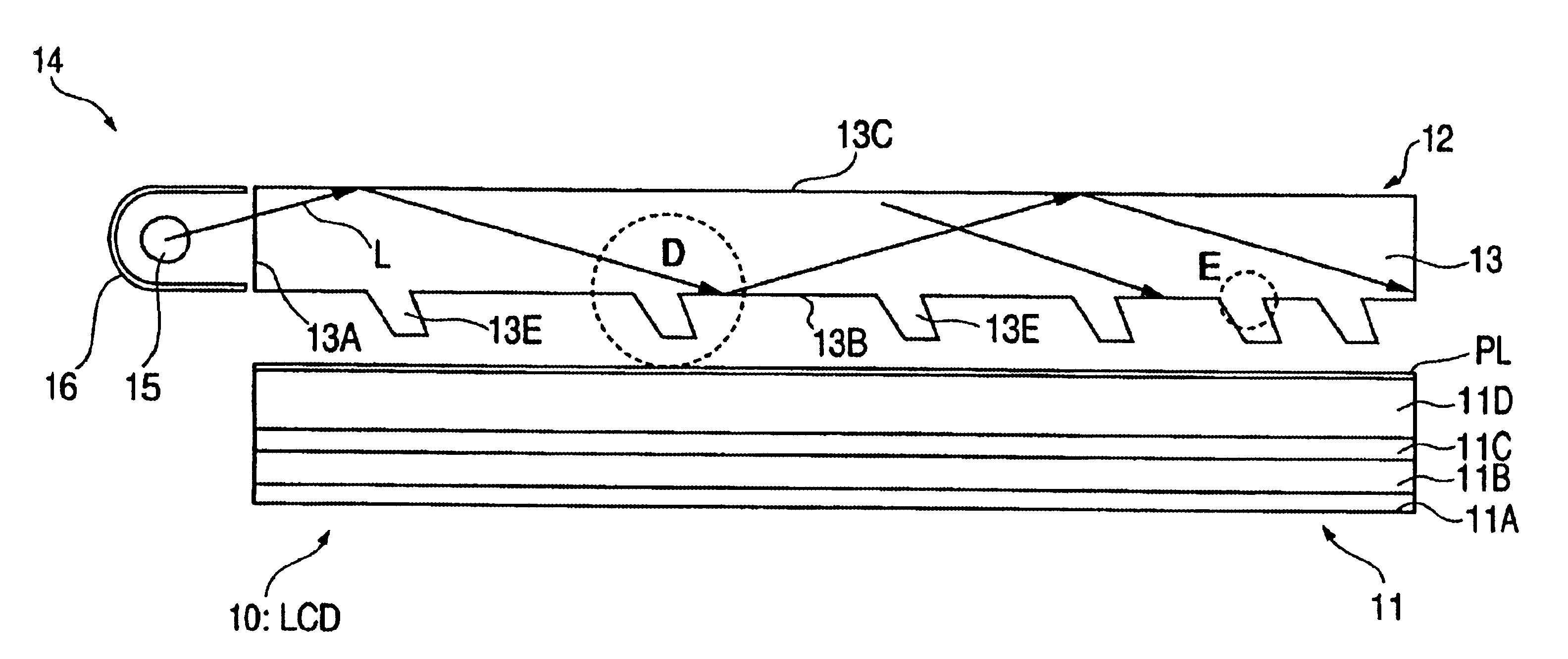
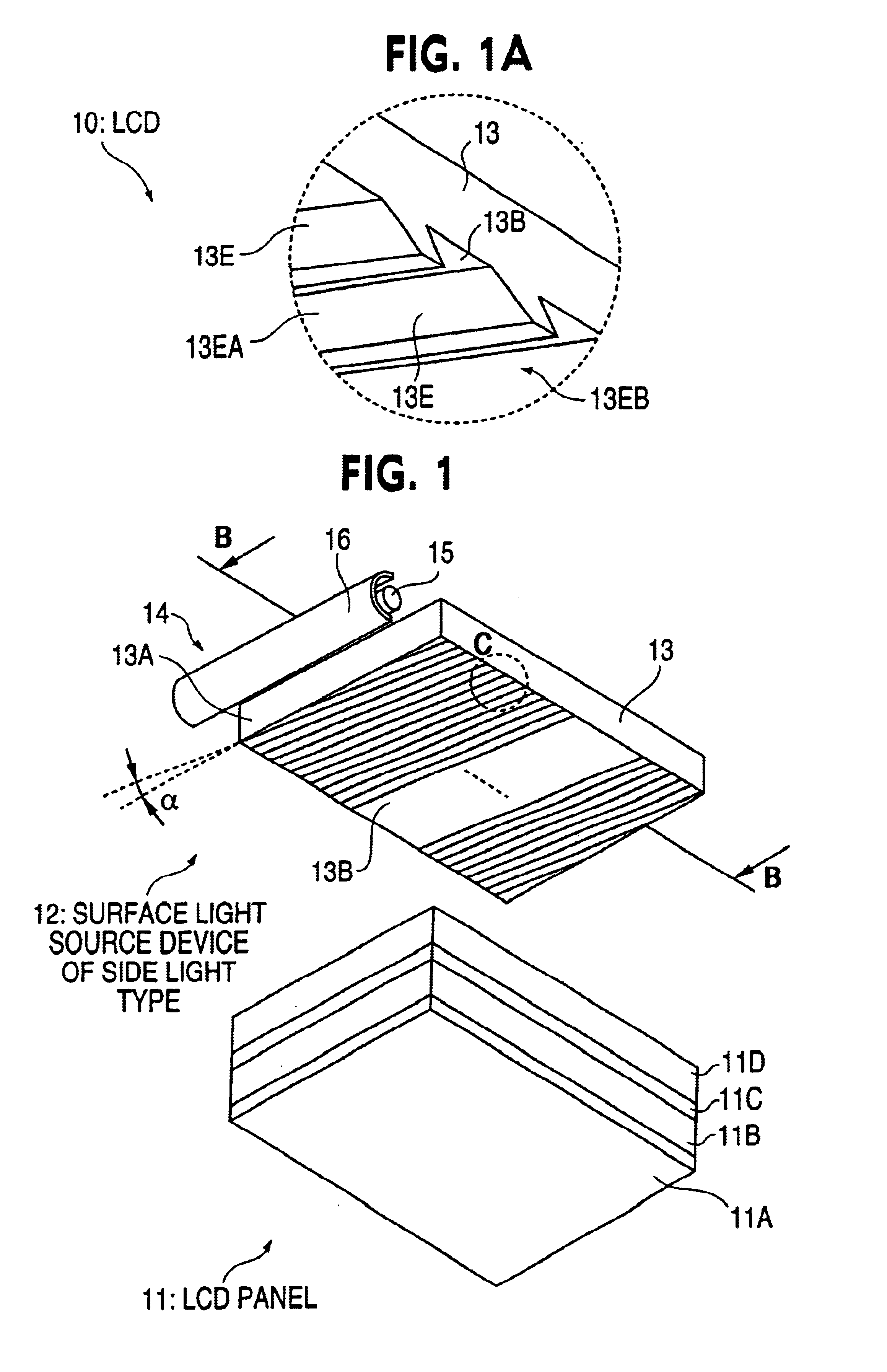
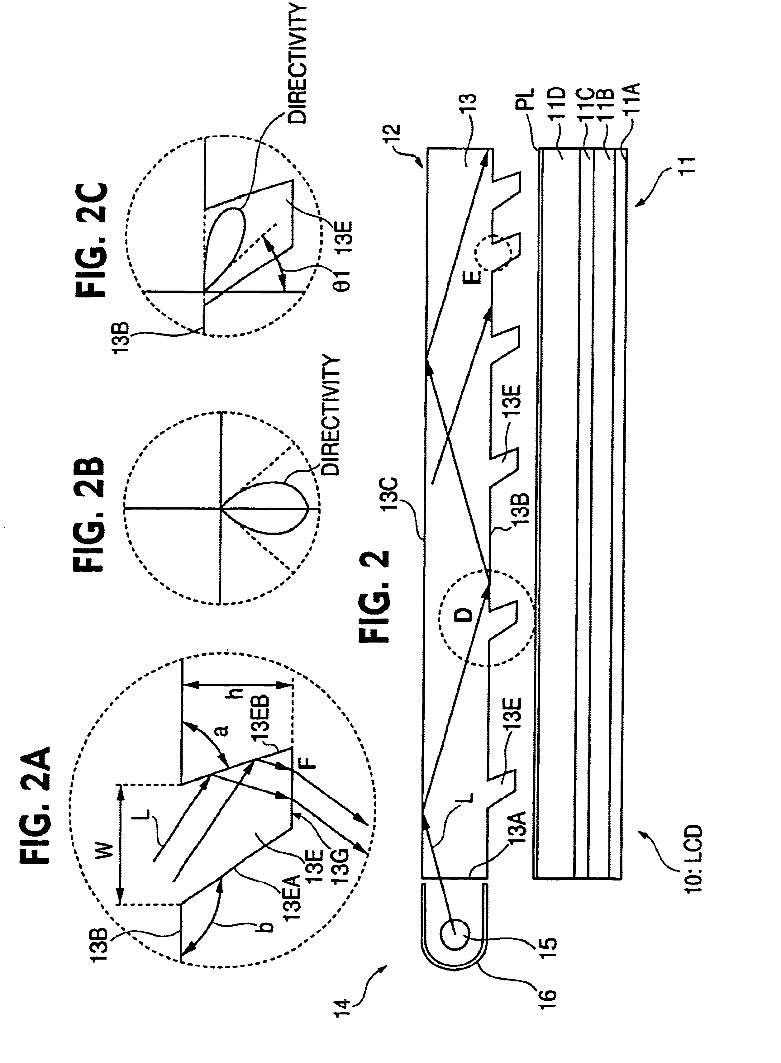
Referring to FIGS. 1 and 2, a liquid crystal display 10 comprises a liquid crystal display panel 11 of reflection type and a surface light source device of side light type 12. The surface light source device 12 is disposed at the outside of the liquid crystal display panel 11 (i.e., at the display screen's side or viewing side) for front-lighting.

The liquid crystal display panel 11 is structured and operates in a well-known manner. That is, the liquid crystal display panel 11 comprises a reflection plate 11A, glass substrate 11B, liquid crystal layer 11C, glass substrate 11D and polarization plate PL which are laminatedly arranged. The glass substrate 11B and glass substrate 11D are provided with matrix-like transparent electrodes (not shown), respectively. The transparent electrodes are driven by a driving circuit (not shown) to control a polarization state of light which transmits through the liquid crystal layer 11C. Accordingly, output light of the liquid crysta...

second embodiment

Second Embodiment

FIGS. 6 and 7 give an exploded perspective view of a liquid crystal display 20 according to a second embodiment. FIG. 9 illustrates light paths of illumination light in the present embodiment. Hereafter, members common to the first embodiment are referenced with a simplified description.

Referring in the first place to FIGS. 6 and 7, the liquid crystal display 20 comprises a reflection-type liquid crystal display panel 11 and a surface light source device of a side light type 22. The surface light source device 22 is disposed at the outside (i.e., at the screen side or viewing side) of the liquid crystal display panel 11 for front-lighting of the panel. The liquid crystal display panel 11 is structured and works as described in the description of the first embodiment.

The surface light source device 22 comprises a guide plate 23 and a primary light source 14. The guide plate 23 has an end face to provide an incidence end face 23A through which the guide plate 23 is s...

third embodiment

Third Embodiment

Referring to FIG. 10, illustrated is a liquid crystal display 30 according to the third embodiment. The liquid crystal display 30 comprises a surface light source device of side light type 32 instead of the surface light source device of side light type 12 or 22. The surface light source device 32 employs a guide plate 33 instead of the guide plate 13 or 23.

Except this, the present embodiment has a skeleton structure the same as that of the aforementioned first or second embodiment. The present embodiment is structured more simply as compared with the aforementioned embodiments. Members common to the first or second embodiment are referenced without repeating the descriptions thereof.

The surface light source device 32 is disposed at the outside (i.e., at the screen side or viewing side) of the liquid crystal display panel 11 for front-lighting of the panel. The liquid crystal display panel 11 is structured and works as described in the description of the first embod...


PUM

PropertyMeasurementUnit
angleaaaaaaaaaa
angleaaaaaaaaaa
Inclination angleaaaaaaaaaa

Abstract

A liquid crystal display includes a surface light source device of a side light type for lighting. On lighting a fluorescent lamp, primary light is introduced into a guide plate and propagates within the guide plate. Much of the illumination light enters into any one of a number of ridges on an emission-function face, being followed by inner impingement upon a flank face, which is more remote from an incidence end face, at an entry angle greater than a critical angle theta 1. Much of the light which has undergone such inner impingement is supplied to a liquid crystal display panel almost frontward via a top face. The ridges are inclined at a predetermined inclination angle alpha with respect to the incidence end face of the guide plate. Inclination angle alpha preferably falls within a range from 5 degrees to 45 degrees, in particular, from 15 degrees to 30 degrees. Employment of size-reduced ridges is realizable, leading to less conspicuous ridges without reducing emission function. Moire fringes are preventable, too. Each ridge may be provided with all or some of a tapered shape, an inclined flank face and foot portions with a stepwise difference.

Description

1. Field of InventionThe present invention relates to a guide plate, surface light source device of side light type and liquid crystal display, in particular, to an improved guide plate, surface light source device of side light type employing the improved guide plate and liquid crystal display employing the surface light source device for illuminating a liquid crystal display panel.2. Related ArtKnown liquid crystal displays belong either to a kind employing a transmission-type liquid crystal display panel or to another kind employing a reflection-type liquid crystal display panel. In general, the former hardly permits ambient light to be used for image formation, leading to employment of surface light source devices such as those of side light type for back-lighting of the transmission-type liquid crystal display panel.On the contrary, the latter enables ambient light to be used for image formation, leading to saving of electric power consumption. However, a device for illuminatin...

Claims


Application Information

Patent Timeline
Patent Type & Authority Patents(United States)
IPC IPC(8): F21V8/00G02B6/00G02F1/1335G02F1/13357
CPCG02B6/0038G02F1/1335
Inventor OHSUMI, KAZUMASA
Owner ENPLAS CORP
Why Eureka
Try Eureka