Alloy type thermal fuse and fuse element thereof

a technology of alloy type thermal fuse and fuse element, which is applied in the direction of thermally actuated switches, heating/cooling contact switches, emergency protective devices, etc., can solve the problems of unable to meet the requirements of environmental protection, the process of drawing the alloy into such a very thin wire is hardly performed, and the operation failure of the fuse element due to self-heating inevitably occurs

Inactive Publication Date: 2004-11-16
UCHIHASHI ESTEC
View PDF25 Cites 14 Cited by
  • Summary
  • Abstract
  • Description
  • Claims
  • Application Information

AI Technical Summary

Benefits of technology

In the above fuses, the alloy compositions are allowed to contain inevitable impurities which are produced in productions of metals of raw materials and also in melting and stirring of the raw materials.

Problems solved by technology

However, the alloy is not suitable to environment conservation which is a recent global request, because, among Pb, Cd, Hg, and Tl which are seemed to be harmful to the ecological system, Pb and Cd are contained in the alloy.
However, the alloy which contains a large amount of Bi is so fragile that a process of drawing the alloy into such a very thin wire is hardly performed.
In such a very thin fuse element, moreover, the relatively high specific resistance of the alloy composition cooperates with the thinness to extremely raise the resistance, with the result that an operation failure due to self-heating of the fuse element inevitably occurs.
As a result, the resistance of the fuse element is raised, and there arises the possibility that an operation failure due to self-heating of the fuse element occurs.
When the lower limit of the compound ratio of Sn is smaller than 2.5%, the amount of Sn is so insufficient that the above-mentioned solid phase transformation cannot be effectively prevented from occurring.
Since In is expensive, the production cost of such a fuse element is inevitably increased.
When the strain is repeated, the sectional area and the length of the fuse element are changed, and the resistance of the fuse element itself becomes unstable.
In other words, the thermal stability cannot be guaranteed.

Method used


Image

  • Alloy type thermal fuse and fuse element thereof
  • Alloy type thermal fuse and fuse element thereof
  • Alloy type thermal fuse and fuse element thereof

Examples


example

(5)

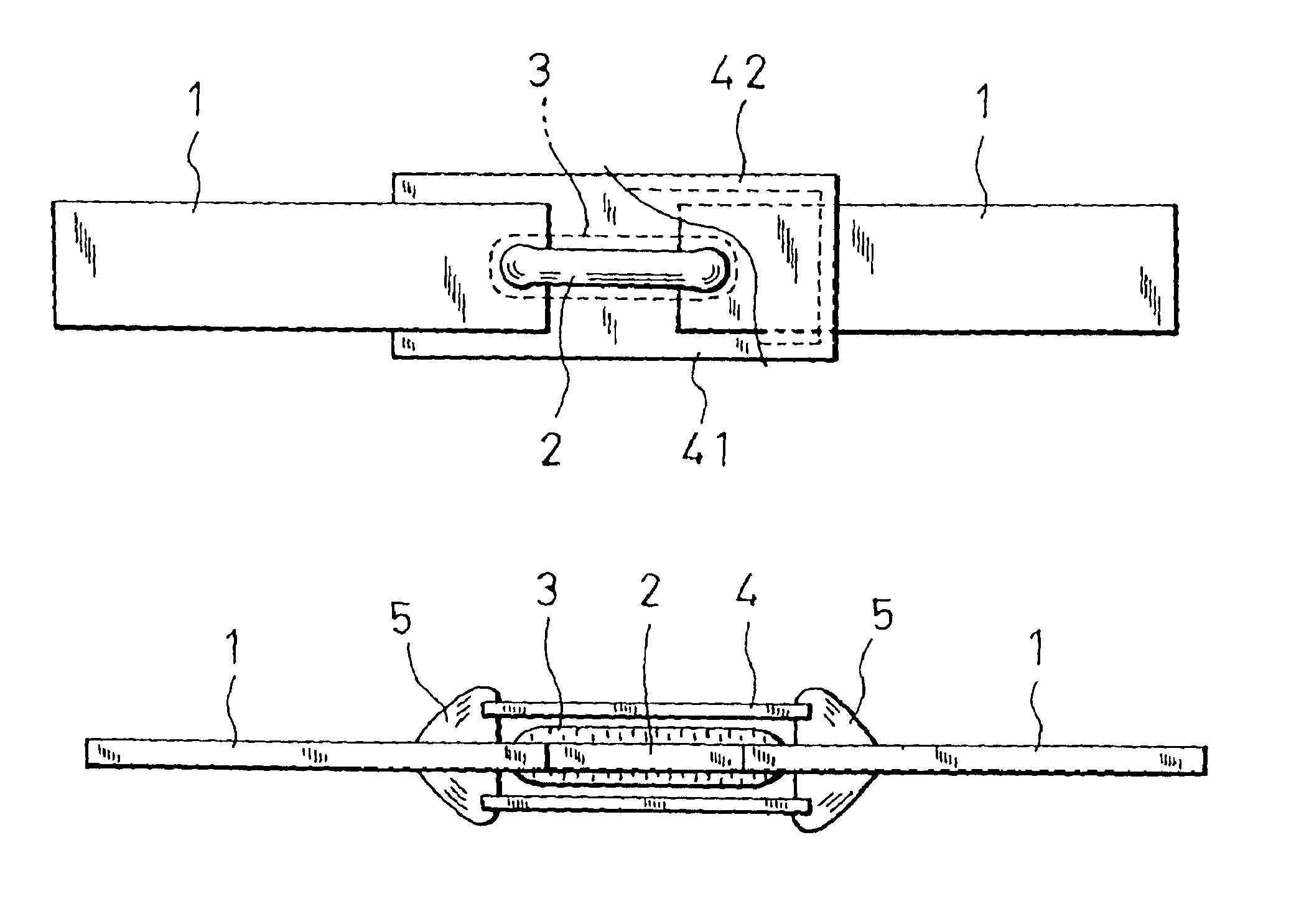
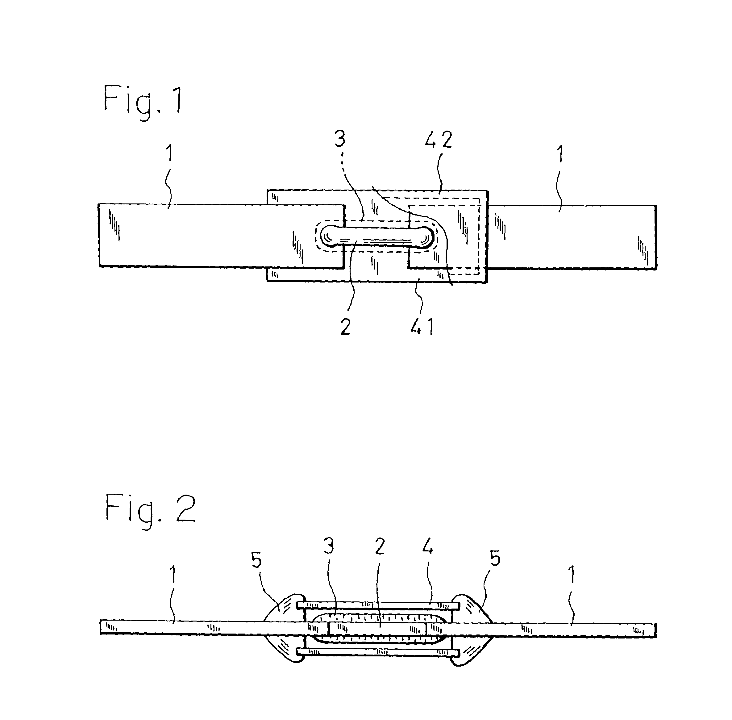
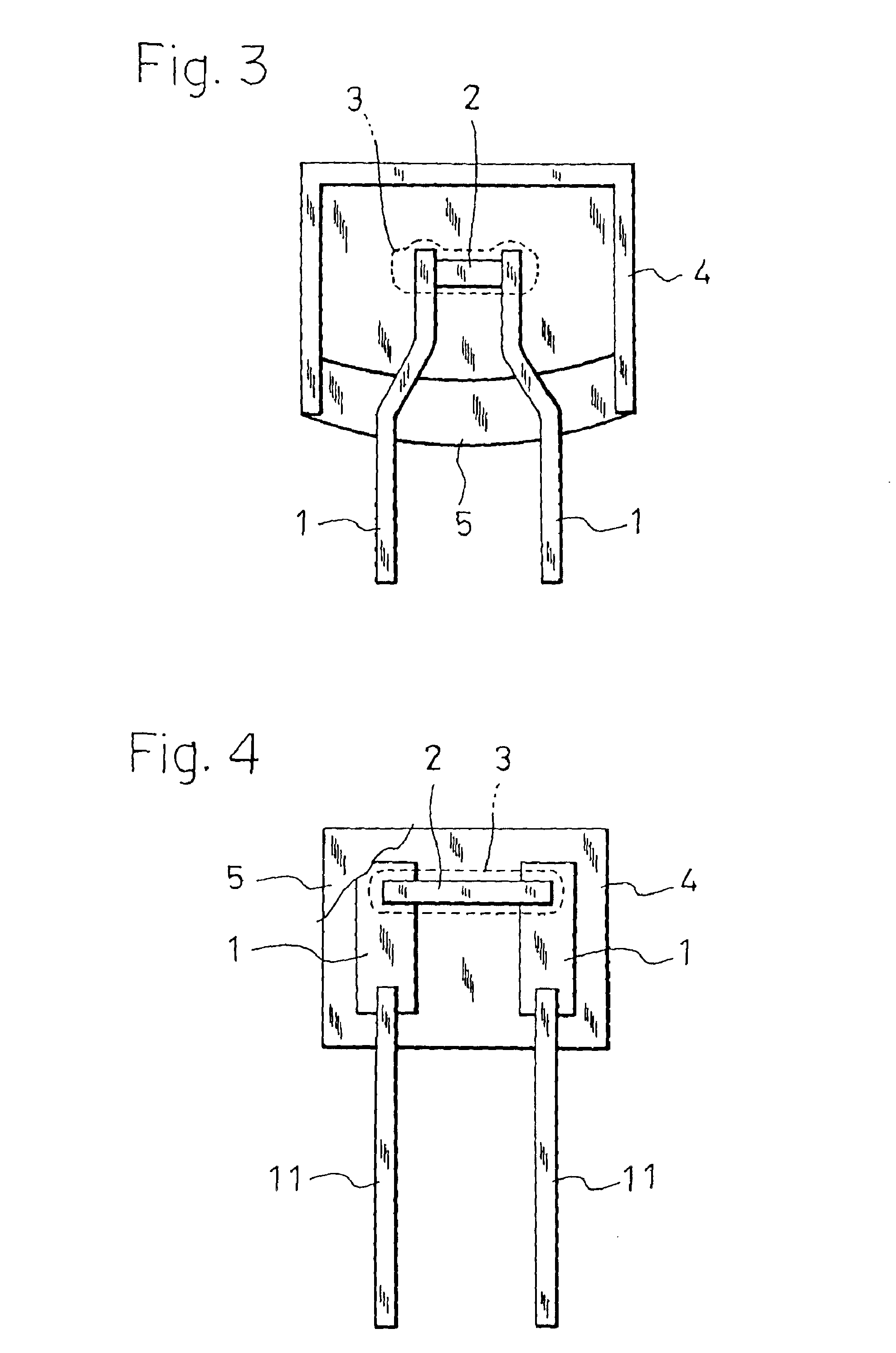
A base material of an alloy composition of 38.6% In, 13.5% Sn, 44.5% Bi, 2.7% Ag, and 0.7% Cu was drawn into a wire of 300 .mu.m.phi. in diameter. The draw-down ratio per dice was 6.5%, and the drawing speed was 45 m / min. In the wire, no breakage occurred. The specific resistance of the wire was measured. As a result, the specific resistance was 38 .mu..OMEGA..multidot.cm.

The wire was cut into pieces of 4 mm, and substrate type thermal fuses were produced with using the pieces as fuse elements in the same manner as Example (1).

The operating temperatures of the resulting specimens were measured. The resulting operating temperatures were within a range of 70.degree. C..+-.1.degree. C. It was confirmed that, under the usual rated current, no influence of self-heating is made. Furthermore, a change in resistance of the fuse element which was caused by the heat cycles, and which may become a serious problem was not observed.

It was confirmed that, in a range of 100 weight parts of a co...


PUM

PropertyMeasurementUnit
operating temperatureaaaaaaaaaa
temperatureaaaaaaaaaa

Abstract

The invention provides a thermal fuse and a fuse element of the low-melting fusible alloy type in which the fuse element has an alloy composition of 37 to 43% In, 10 to 18% Sn, and the balance Bi. As a result, the operating temperature is in the range of 65 to 75° C., requests for environment conservation can be satisfied, the diameter of the fuse element can be made very thin or reduced to about 300 mumphi, self-heating can be suppressed, and the thermal stability can be satisfactorily guaranteed.

Description

The present invention relates to an alloy type thermal fuse, more particularly to improvement in an alloy type thermal fuse of an operating temperature of 65 to 75.degree. C., and also to a fuse element which constitutes such a fuse, and which is made of a low-melting fusible alloy.DESCRIPTION OF RELATED ARTIn a conventional alloy type thermal fuse, a low-melting fusible alloy piece to which a flux is applied is used as a fuse element. When an electric apparatus on which such a fuse is mounted abnormally generates heat, therefore, a phenomenon occurs in which the low-melting fusible alloy piece is liquefied by the generated heat, the molten metal is spheroidized by the surface tension under the coexistence with the flux that has already melted, and the alloy piece is finally broken as a result of advancement of the spheroidization, whereby the power supply to the apparatus is interrupted.The first requirement which is imposed on such a low-melting fusible alloy is that the solid-liq...

Claims


Application Information

Patent Timeline
Patent Type & Authority Patents(United States)
IPC IPC(8): H01H37/00H01H37/76C22C12/00
CPCH01H37/761H01H2037/768
Inventor TANAKA, YOSHIAKI
Owner UCHIHASHI ESTEC
Why Eureka
Try Eureka