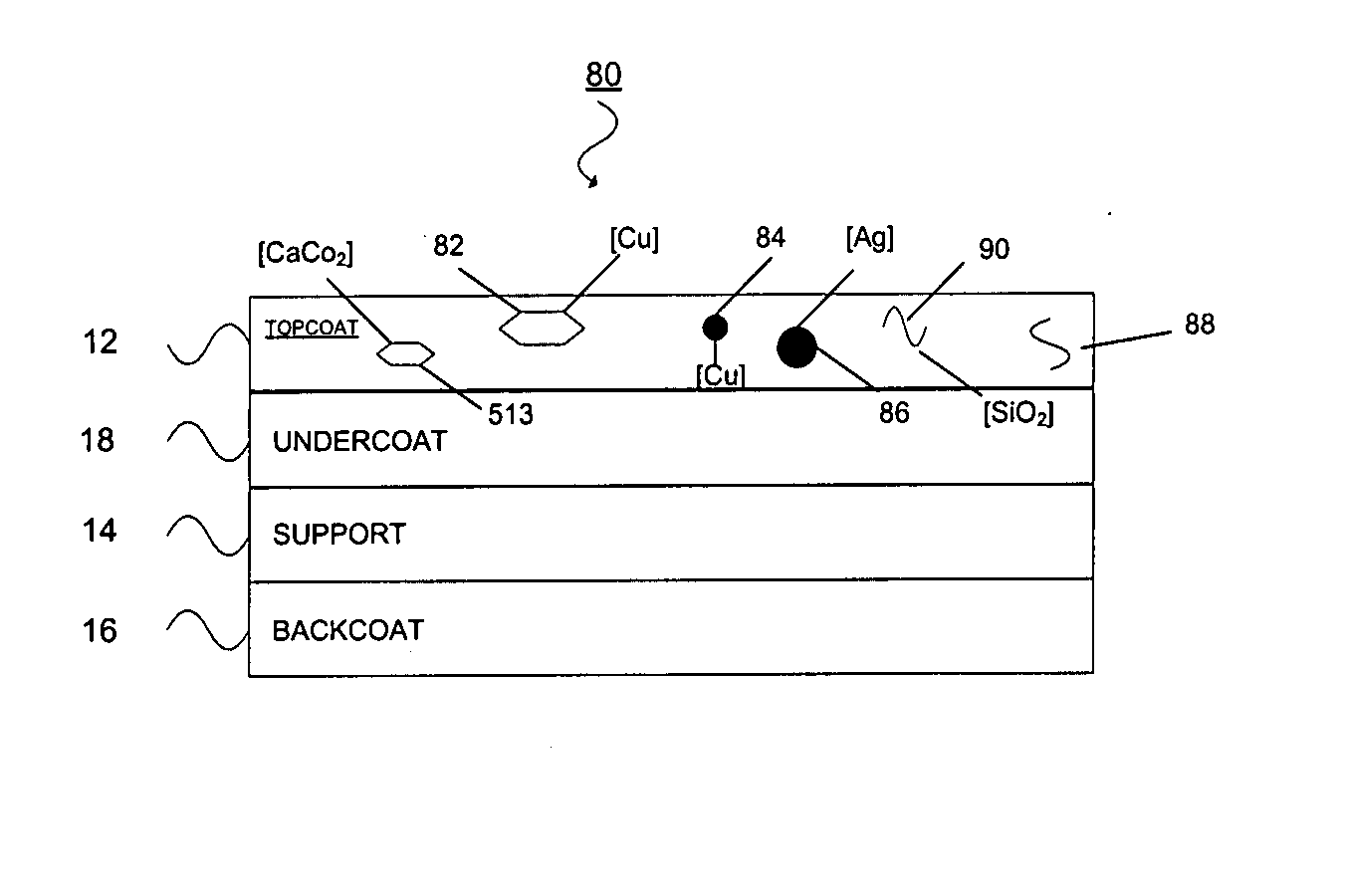
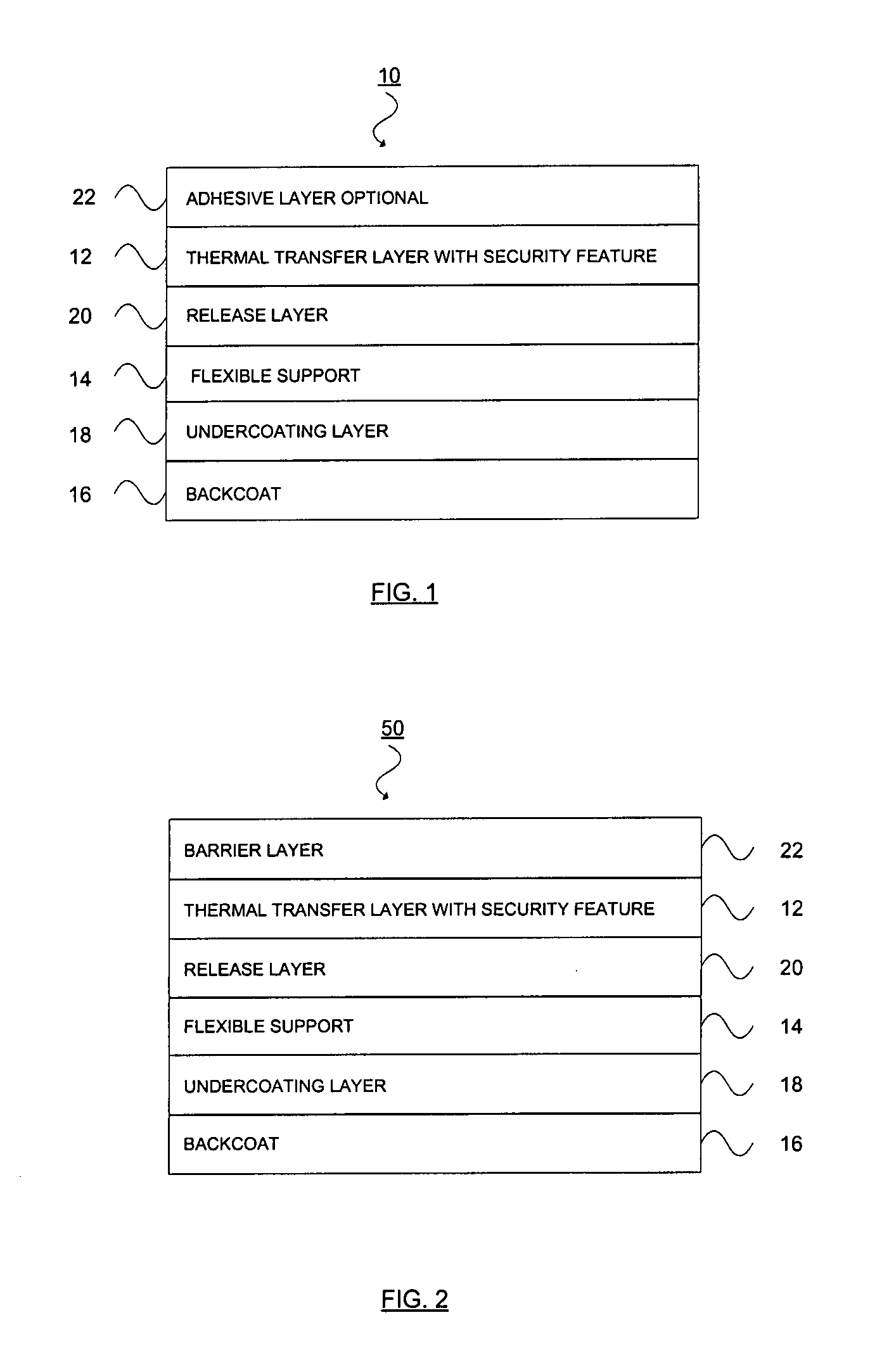
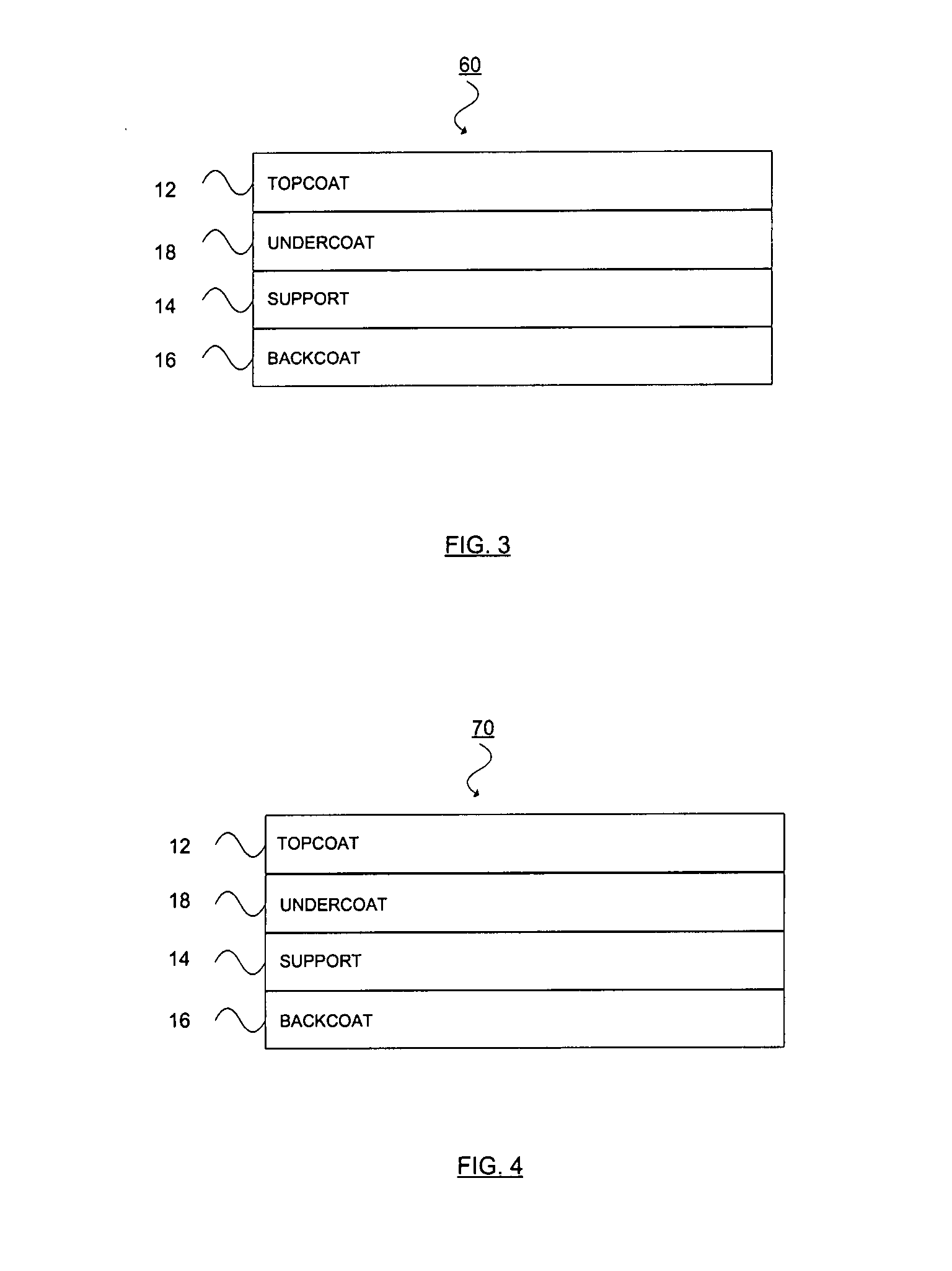
Thermal transfer ribbon

a technology of thermal transfer ribbon and transfer ribbon, which is applied in the direction of thermal imaging, inking apparatus, transportation and packaging, etc., can solve the problems of counterfeiters or diverters being difficult to detect, the product from one market to another and the concealment security device cannot be immediately detected with human senses

Inactive Publication Date: 2008-04-17
INT IMAGING MATERIALS
View PDF99 Cites 52 Cited by
  • Summary
  • Abstract
  • Description
  • Claims
  • Application Information

AI Technical Summary

Benefits of technology

[0005] A thermal transfer printing medium comprised of a thermal transfer layer, wherein: (a) said thermal transfer layer is comprised of a first taggant, wherein said first taggant comprises a fluorescent compound with a first excitation wavelength; (b) said first excitation wavelength is selected from the group consisting of wavelengths of less than 400 nanometers, wavelengths of greater than 700 nanometers, and mixtures thereof; (c) said thermal transfer layer is comprised of a first colorant; (d) said thermal transfer layer has a light transmittance of at least about 10 percent when illuminated by light having said first excitation wavelength of said first taggant; (e) when said thermal transfer layer is printed onto a white polyester substrate with a gloss of at least about 84, a surface smoothness Rz value of 1.2, and a reflective color represented by a chromaticity (a) of 1.91 and (b) of −6.79 and a lightness (L) of 95.63, when expressed by the CIE Lab color coordinate system, and when such printing utilizes a printing speed of 2.5 centimeters per second and a printing energy of 3.2 joules per square centimeter, a printed substrate is produced wherein: 1. said printed substrate has a reflective color represented by a chromaticity (a) of from −15 to 15 and (b) from −18 to 18, and said printed substrate has a lightness (L) of less than about 35, when expressed by the CIE Lab color coordinate system; and 2. when said printed substrate is illuminated with light source that excites said first taggant with said first excitation wavelength, said printed substrate produces a light fluorescence with a wavelength in the range of from about 300 to about 700 nanometers.

Problems solved by technology

In recent times, the diversion of products from one market to another has also become problematic.
Covert security devices cannot be immediately detected with human senses.
Covert security devices have the advantage of being less easily detectable without the aid of an external device, making detection more difficult for the counterfeiter or diverter, but they have a disadvantage in that they require less readily available equipment for detection, making it difficult to have a detector at every point along the distribution chain.
Forensic markers are typically added at a very low level to inks and materials such that they may appear as background noise in an elemental analysis.
As described above, forensic security markers have the advantage of difficult detectability by the counterfeiter or diverter, and the disadvantage of requiring more specialized equipment for detection.
This patent cautions against adding non-luminescent pigments to the composition as their presence adversely affects the fluorescent quality, even at levels as low as one percent of the non-luminescent material.
These patents do not disclose ribbons containing marking compositions which are invisible to the human eye.
The problem of interference by visible light absorbing colorants on the detection of markers is amplified when the amount of such markers is relatively small.
However, detection of such markers becomes difficult because the physical properties of the ink composition are dominated by the majority of components in the printing composition.
For example, the detection of a fluorescent marker may be compromised if the marker is incorporated into an ink composition in which the other components either absorb the light used to excite the fluorescence of the marker or the light emitted by the marker's fluorescence.
When low concentrations of fluorescent markers are employed in the ink composition, interference from the other components is especially problematic.
This, however, complicates the construction of the thermal transfer ribbon, and other design considerations must be taken into account for this method to be successful.
With increasing addition amounts, there is growing impairment of the brilliance of the fluorescent pigments, the fluorescence power, and color purity due to occurring interferences.
Still higher addition amounts lead to almost total extinction.” They go on to say that, at acceptable levels of non-luminescent pigments for fluorescence detection, the color and density are only minimally changed so no benefit is provided.
The inventors state “Problems can still arise when a commercial black ink is to be employed in the printed matter.
The major obstacle to achieving similarity between secure and non-secure versions of thermal transfer ribbons is that such ribbons typically include carbon black in the ink layer (15 percent or more of the total ink composition by weight is typical), and many of the security taggants function by absorption, emission, or both, of electromagnetic radiation which is absorbed by the carbon black.
When the radiation is absorbed by the carbon black, it is not available for excitation of the taggant.
Further, even when there is sufficient absorption by the taggant to generate the desired response, the emitted radiation by the taggant can also be absorbed by the carbon black, and thus not be detectable.
The excitation issues seem to be the greater challenge.
A disadvantage with these materials is the fact that, using IR radiation, only energy stored beforehand—for example by excitation with visible light—is extracted.
Continuous emission of visible light under IR radiation is therefore not possible with these IR-stimulable materials.
Disadvantages with these active lattices are that they are often difficult to produce with the exclusion of oxygen and that there is a tendency, depending on the composition of the active lattice, to instability in practical application, for example in application at high temperatures.”
Upon heating, the propellant evaporates to increase the internal pressure at the same time as the shell softens, resulting in significant expansion of the microspheres.
However, even if a suspending agent has been added during the production of the microspheres, this may have been washed off at a later stage and could thus be substantially absent from the final product.” In one embodiment, the microspheres may comprise one or more taggant materials.
However, upon application of heat above the thermal transfer temperature, expansion will occur such that a significant change in the texture and appearance of the printed image results.
Any one printing pass would not be sufficient to discern the entire image.

Method used


Image

  • Thermal transfer ribbon
  • Thermal transfer ribbon
  • Thermal transfer ribbon

Examples


example 1

[0247] This example illustrates the preparation of a thermal transfer ribbon that contains an essentially colorless photochromic dye that, upon exposure to 400 nanometer ultraviolet light or sunlight, becomes brightly colored and fades back to colorless when removed from the source of radiation. In addition, the thermal transfer layer of the ribbon of this example is comprised of an invisible ultraviolet fluorescing pigment with an excitation wavelength of 365 nanometers that, when exposed to this wavelength, fluoresces with an intense, bright color until removed from the source of radiation. Additionally, such thermal transfer layer also is comprised of taggant material that is incorporated in low concentrations and designed to be detectable by reader assemblies specific to the composition of the taggant. In particular, for this example, an up-shifting phosphor taggant and infrared laser detector were selected. The infrared laser detector signals only the presence of the taggant in...

example 2

[0252] A solution “A” was made by mixing 41.77 grams of solvent-grade 2-butanone and 28.13 grams solvent-grade toluene and heating the mixture to 70 degrees Celsius. After reaching this temperature, 8.7 grams of VY200 co-polyester (purchased from Bostik) and 1.68 grams Dynapoll 411 polyester (purchased from Degussa Corp, 65 Challenger Rd., Ridgefield, N.J.) were added and stirred until completely dissolved. To this solution were added 1.16 grams of 382 ES-HMW bisphenol-A fumarate polyester (purchased from Reichhold Chemical, Triangle Research Park, North Carolina); and 17.36 grams of BR87 polymethylmethacrylate (purchased from Dianal America Corporation) was added and stirred until completely dissolved and then cooled to room temperature.

[0253] An ink was prepared by mixing 59.21 grams of Solution “A,” 0.42 grams of Solsperse 24000 dispersant (purchased from Noveon, Inc. Cleveland, Ohio) and 27.74 grams of an advanced optical effect pigment Dynacolor BG (Englehard Corp., Appearance...

example 3

[0256] In this example a solution “B” was made by dissolving 6.58 grams of KeyFluor Red IR dye (Keystone Aniline Corp, Chicago, Ill.) in 94.32 grams of 2-butanone. Solution “B” was then added at 11.50 grams to 87.0 grams of the solution “A” described in Example 1 and stirred until homogenous. To this ink were then added 1.5 grams of an up-converting phosphor LUC-O-08 (Lorad Chemical Corporation, St. Petersburg, Fla.). Fifty grams of ceramic media were added to the ink, and the ink was allowed to roll on a ball mill roller for 30 minutes to aid in homogeneity. The media was then filtered out of the ink, and an ink ribbon was coated and printed as described in Example 1.

[0257] The thermally printed colored images of this example displayed three different effects. First noted was an optically variable change in visual color from blue to green when the angle of viewing the image was changed from 180 degrees to 90 degrees in normal lighting conditions, as described in Example 2. Second ...


PUM

PropertyMeasurementUnit
wavelengthsaaaaaaaaaa
light transmittanceaaaaaaaaaa

Abstract

A thermal transfer printing medium that contains a thermal transfer layer which contains a first taggant and colorant, wherein: the first taggant comprises a fluorescent compound with an excitation wavelength selected from the group consisting of wavelengths of less than 400 nanometers, wavelengths of greater than 700 nanometers. When the thermal transfer layer is printed onto a white polyester substrate with a gloss of at least about 84, a surface smoothness Rz value of 1.2, and a reflective color represented by a chromaticity (a) of 1.91 and (b) of −6.79 and a lightness (L) of 95.63, when expressed by the CIE Lab color coordinate system, and when such printing utilizes a printing speed of 2.5 centimeters per second and a printing energy of 3.2 joules per square centimeter, a printed substrate with certain properties is produced. The printed substrate has a reflective color represented by a chromaticity (a) of from −15 to 15 and (b) from −18 to 18, and the printed substrate has a lightness (L) of less than about 35, when expressed by the CIE Lab color coordinate system. When the printed substrate is illuminated with light source that excites the first taggant with an excitation wavelength selected from the group consisting of wavelengths of less than 400 nanometers, wavelengths greater than 700 nanometers, the printed substrate produces a light fluorescence with a wavelength of from about 300 to about 700 nanometers.

Description

CROSS-REFERENCE TO RELATED PATENT APPLICATIONS [0001] This patent application claims priority based upon U.S. patent application 60 / 840,732, filed on Aug. 29, 2006. The entire disclosure of this provisional patent application is hereby incorporated by reference into this specification.FIELD OF THE INVENTION [0002] A thermal transfer ribbon adapted to print an overt, covert or forensic level security mark onto a substrate. BACKGROUND OF THE INVENTION [0003] U.S. Pat. No. 6,174,400 of Krutak et al. describes near infrared fluorescent security thermal transfer printing and marking ribbons. In this patent, the “prior art” is discussed, and it is disclosed that “ . . . thermal transfer ribbons incorporating invisible marking compound which are not visible to the unaided human eye . . . ” are not known. In such patent, the inventors disclose that, with regard to the infrared preferred embodiment (in which a near infrared fluorescer [NIFR] is incorporated into an ink composition), “When th...

Claims


Application Information

Patent Timeline
Patent Type & Authority Applications(United States)
IPC IPC(8): B41M5/40
CPCB41M5/385B41M5/41B41M2205/06Y10T428/24942Y10T428/24843Y10T428/24926Y10T428/252Y10T428/24901
Inventor ESKRA, JENNIFERGEDDES, PAMELAHARRISON, DANIELJALBERT, CLAIREMARGINEAN, BARRYPRZYBYLO, JOHN
Owner INT IMAGING MATERIALS
Why Eureka
Try Eureka