Mounting tool for linear encoders

a technology of linear encoders and mounting tools, which is applied in the direction of manufacturing tools, instruments, walking sticks, etc., can solve the problems of time-consuming and labor-intensive process of attaching linear encoders to one or more machine axes

Inactive Publication Date: 2004-11-23
HEIDENHAIN CORP
View PDF34 Cites 12 Cited by
  • Summary
  • Abstract
  • Description
  • Claims
  • Application Information

AI Technical Summary

Problems solved by technology

Accordingly, the process of attaching linear encoders to one or more of the machine axes can be a time consuming process.

Method used


Image

  • Mounting tool for linear encoders
  • Mounting tool for linear encoders
  • Mounting tool for linear encoders

Examples


Embodiment Construction

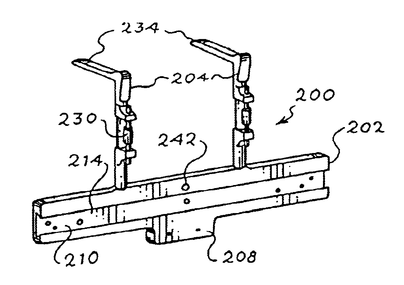
FIG. 12 schematically shows a mounting tool 200 that includes a template in the form of base 202 and a pair of identical height gages 204 attached thereto. As shown in FIG. 13, the base 202 has a T-like shape with a longitudinal body 206 having a length of approximately 113 / 4", a height of approximately 21 / 4" and a thickness of approximately 3 / 8". A lower portion 208 is centrally located with respect to the longitudinal body 206 and has a length of approximately 21 / 4". The longitudinal body 206 and the lower portion 208 are preferably integral with one another and made of Aluminum.

As shown in FIG. 13, a slot 210 is formed in the body 206 so as to extend along the entire length of the body 206 in a direction x that is parallel to a longitudinal dimension of the base 202. The slot 210 forms an opening 212 extending along the same direction that the slot 210 extends. The opening 212 faces a planar portion 214 of the base 202. Besides the planar portion 214, the slot 210 is formed from ...


PUM


Abstract

A mounting tool that includes a base extending along a first direction that is parallel to a longitudinal dimension of the base and a height gage attached to the base. The height gage includes a first leg attached to the base and extending along a second direction that is not parallel to the first direction and a second leg attached to the first leg and comprising a support portion extending along a third direction that is not parallel to the second direction.

Description

1. Field of the InventionThe present invention relates to a mounting tool for attaching a measuring device to a machine tool. In particular, the present invention regards a mounting tool for attaching a linear encoder to a machine tool.2. Discussion of Related ArtIt is well known to retrofit one or more axes of existing, manually operated machine tools with linear encoders. The linear encoders generate position dependent output signals so that the machine tools can be operated as numerically controlled machines.An example of a system for retrofitting manually operated machine tools with linear encoders is the bracket kit sold by Acu-Rite of Jamestown, N.Y. under Model No. 385072-17. As shown in FIG. 1, the system 100 includes a linear encoder 102 for attachment to the longitudinal axis 104 of the machine tool 106. As shown in FIG. 2, a reading head 108 is placed adjacent to the bottom of the scale case 110 that contains the linear encoder 102. The reading head 108 is moved so that a...

Claims


Application Information

Patent Timeline
Patent Type & Authority Patents(United States)
IPC IPC(8): B23Q17/22G01D5/26G01D5/347
CPCG01D5/34746B23Q17/22
Inventor BRUMBAUGH, MICHAEL
Owner HEIDENHAIN CORP
Why Eureka
Try Eureka