Linear encoder

a linear encoder and encoder technology, applied in the field of linear encoders, can solve the problems of inability to encode, hole b>, machining and discharge machining, etc., and achieve the effect of reducing the length of through holes, facilitating milling machining, and easy formation of long holes for

Active Publication Date: 2016-01-14
OKUMA CORP
View PDF11 Cites 12 Cited by
  • Summary
  • Abstract
  • Description
  • Claims
  • Application Information

AI Technical Summary

Benefits of technology

[0011]According to the present invention, a part of the pillar closer to the detection head holding unit and a part of the detection head holding unit closer to the pillar are bored by a thickness larger than the thickness of the pillar. With the above, it is possible to reduce the length of the through hole. Thus, it is possible to integrally mold the slider enclosure including the through hole by means of lost wax casting, die casting, or the like. Further, even when integral molding is not possible, depending on the length of a through hole, it is possible to achieve a through hole shorter than that of a conventional slider enclosure, and to make the root portion of a milling tool as thick as the thickness of the pillar or even thicker, which facilitates milling machining for formation of a through hole. With the above, it is possible to readily form a

Problems solved by technology

However, it is not possible to form the through hole 26 of the detection head holding unit 23 and the pillar 24 by means of integral molding, as the diameter of the hole is very small while the length thereof is as long as five times the hole diameter.
Further, in the case where the through hole is formed in post processing, there are available only drill machining and discharge machining with high machining cost, and it is necessary to form a plurality of holes when there are many wires.
Still further, as the pillar is very thin, machining defect may likely be caused at the time of drill machining by a drill by breaking through the surface of the pillar.
Yet further, while a t

Method used


Image

  • Linear encoder
  • Linear encoder
  • Linear encoder

Examples


Embodiment Construction

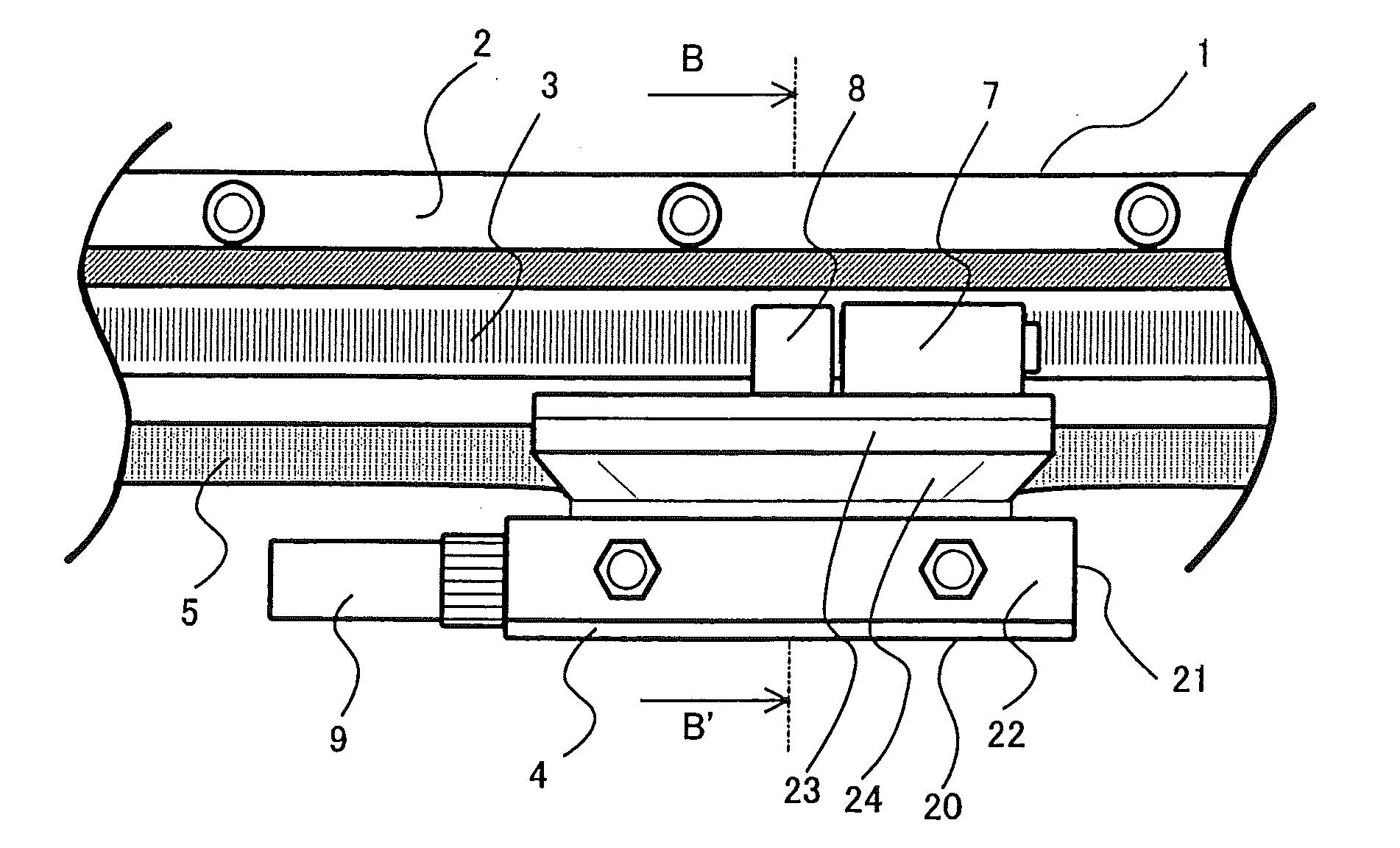
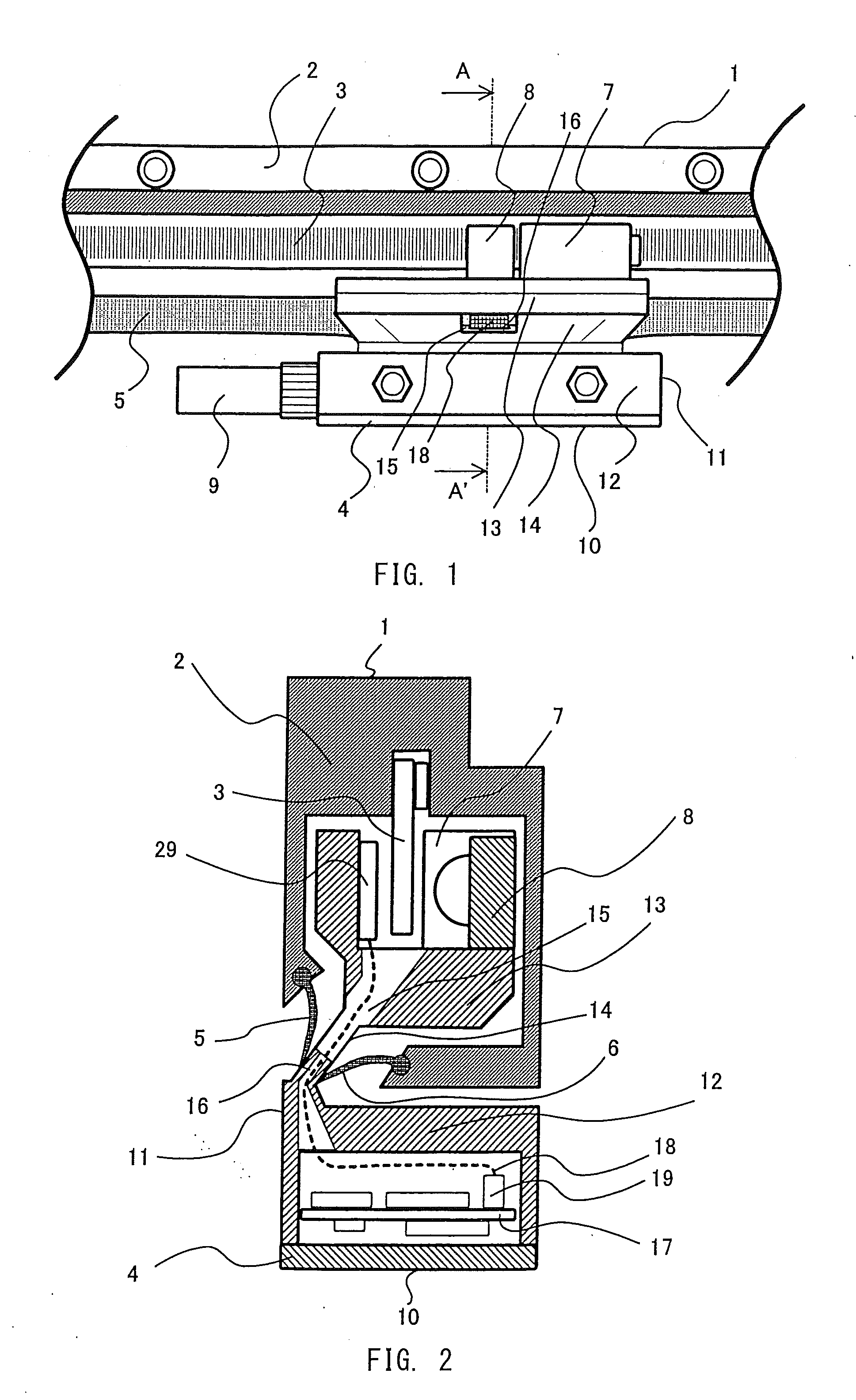
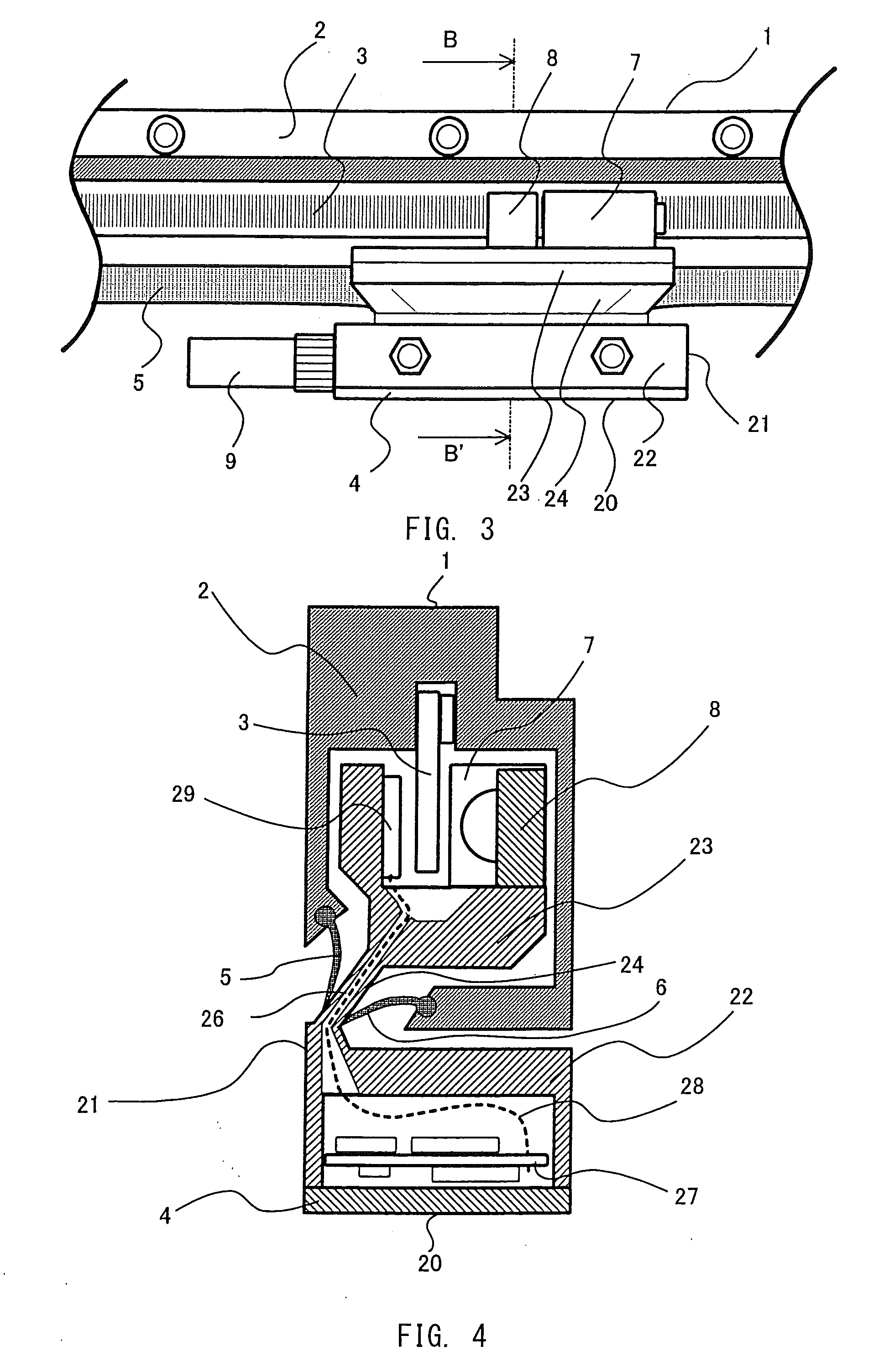
[0018]In the following, the present invention will be described with reference to the drawings. FIG. 1 shows a specific structure of a linear encoder according to the present invention. FIG. 2 is a cross sectional view along line A-A′ in FIG. 1. Note that for ready understanding, the seal 6 and the upper surface of the scale enclosure 2 (the right end surface in FIG. 2) are not shown in FIG. 1. In FIGS. 1 and 2, a member having the same function as that in FIGS. 3 and 4 is given the same reference numeral, and is not described. The detection head holding unit 13 of the slider enclosure 11 and a part of the pillar 14 have a shape formed by boring a part up to a position immediately before a position where the pillar 14 contacts the seals 5, 6 on the side of the detection head holding unit 13 by a thickness larger than the thickness of the pillar 14.

[0019]That is, as is obvious from the drawing, the detection head holding unit 13 is fully accommodated in the hollow space formed inside...


PUM


Abstract

To provide a linear encoder including a scale unit and a slider that slides along the scale unit, wherein the slider includes a slider enclosure including a slider holding unit, a detection head holding unit mounted inside a scale enclosure of the scale unit, and a pillar extending between the outside and inside of the scale enclosure to connect these two holding units, and a part of the pillar closer to the detection head holding unit and a part of the detection head holding unit closer to the pillar are bored by a thickness larger than a thickness of the pillar.

Description

PRIORITY INFORMATION[0001]The present invention claims priority under 35 U.S.C. §119 to Japanese Application No. 2014-142006 filed on Jul. 10, 2014, the entire content of which is incorporated herein by reference.TECHNICAL FIELD[0002]The present invention relates to a linear encoder to be assembled into a machining tool, a semiconductor manufacturing device, or the like, for determining a position of a movable shaft.BACKGROUND ART[0003]FIG. 3 shows a specific structure of a conventional linear encoder. FIG. 4 is a cross sectional view along line B-B′ in FIG. 3. As shown in the cross section in FIG. 4, a scale unit 1 of the conventional linear encoder shown in FIG. 3 includes a scale enclosure 2 that is open at and around a corner defined by the bottom surface thereof and the rear surface thereof, and has a main scale 3 secured inside the scale enclosure 2. The main scale 3 is made of glass, and has a scale made of metallic thin film and carved in matrix on the surface thereof at a c...

Claims


Application Information

Patent Timeline
IPC IPC(8): G01D5/347
CPCG01D5/34746G01D5/34753
Inventor HAYASHI, YASUKAZUFUKUI, NORIYUKI
Owner OKUMA CORP
Why Eureka
Try Eureka