Method of manufacturing antennas using micro-insert-molding techniques

a manufacturing method and technology of antennas, applied in the direction of waveguide devices, resonant antennas, other domestic articles, etc., can solve the problems of limiting the industrial design of products, compromising total cost, and height is also the most difficult physical feature to maintain at tight tolerances

Inactive Publication Date: 2004-11-23
OAE TECH INC
View PDF13 Cites 52 Cited by
  • Summary
  • Abstract
  • Description
  • Claims
  • Application Information

AI Technical Summary

Problems solved by technology

There are various realizations of internal antennas for portable devices, but the cost and size of these approaches often limits the industrial design of the product or compromises total cost.
Height is also the most difficult physical feature to maintain at tight tolerances.
But due to the three dimensional nature of the end product, the antenna's height is far less controllable.
This induces significant variability in the height of the antenna.
Also, even if the antenna is fabricated perfectly, the final height realized in the customer's product is susceptible to variation due to assembly tolerances.
Existing antenna solutions require significant space, add weight, increase cost, and most importantly, often compromise production yields.
Hence, one of the major cost drivers when fabricating high-volume antennas is reproducibility of the antennas themselves.

Method used


Image

  • Method of manufacturing antennas using micro-insert-molding techniques
  • Method of manufacturing antennas using micro-insert-molding techniques
  • Method of manufacturing antennas using micro-insert-molding techniques

Examples


Embodiment Construction

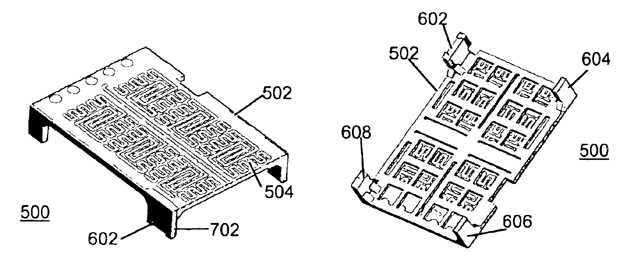
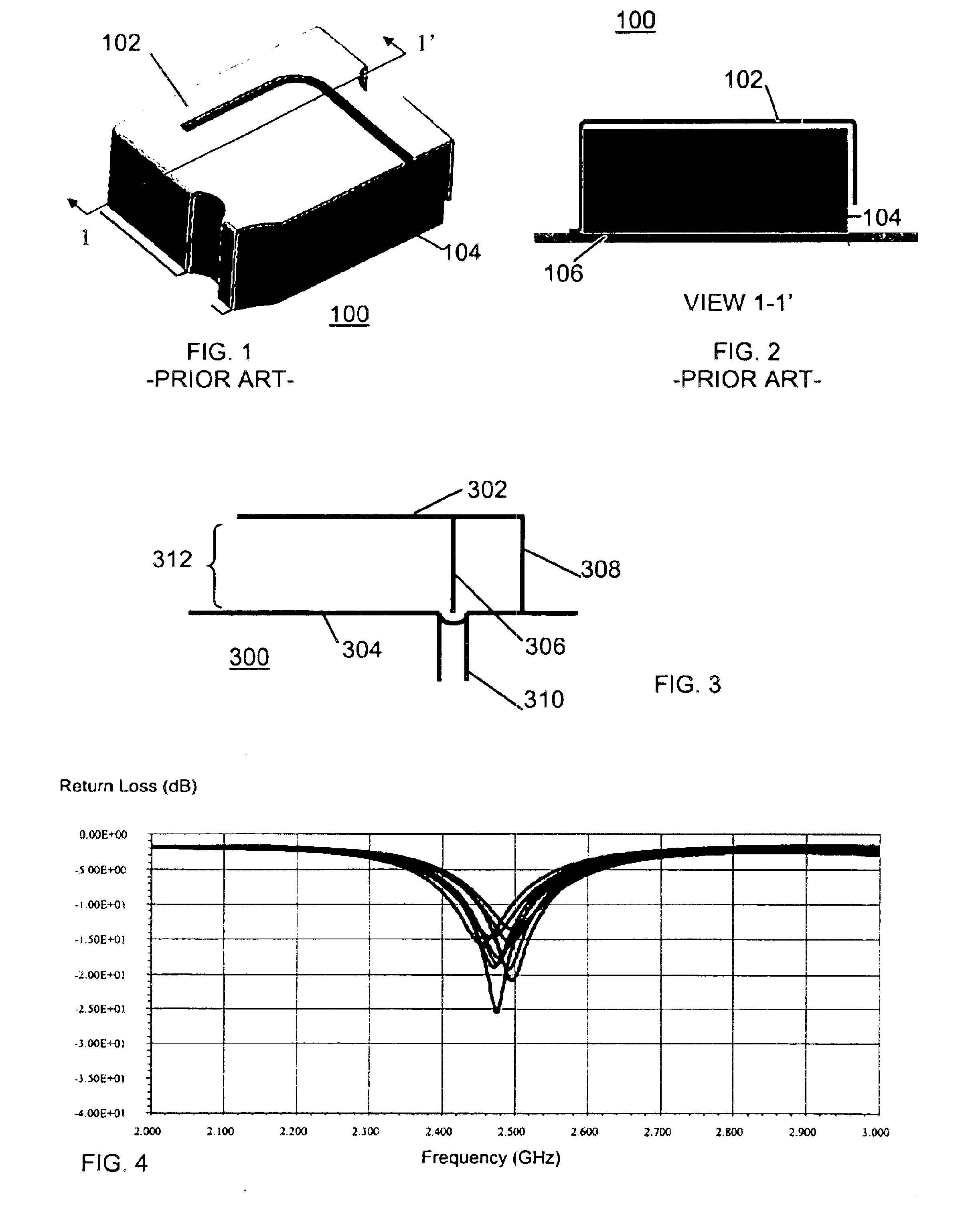
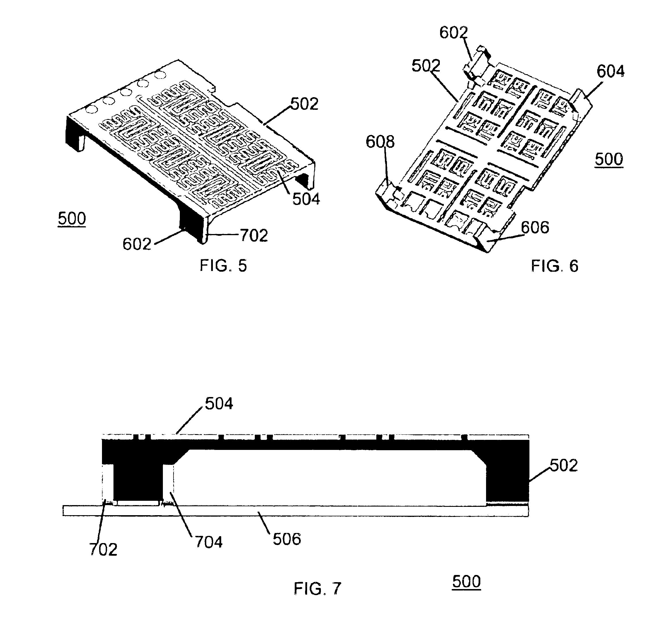
The proposed antenna departs from the antenna shown in FIGS. 1 and 2 by using micro-insert molding techniques to manufacture the antenna with much more control on mechanical tolerances and significantly lower total cost. The techniques disclosed here in may be applied to the widest variety of antennas and they have particular application to surface mount antennas to be mounted directly to the surface of a printed circuit board. The main printed circuit board (PCB) of the product forms the ground plane for the antenna. Many types of antennas can be mounted above a ground plane. Bent-wire monopoles, dipoles, patches, shorted patches, and Planar Inverted F Antennas (PIFA) are all examples of antenna types compatible with mounting above a finite size ground plane.

One particular type of antenna which may benefit from the disclosed method and apparatus is a planar inverted F antenna or PIFA. FIG. 3 shows a cross sectional view of a PIFA 300. The PIFA 300 includes an antenna 300, a ground ...


PUM

PropertyMeasurementUnit
heightaaaaaaaaaa
heightaaaaaaaaaa
distanceaaaaaaaaaa

Abstract

An antenna includes a precision micro-molded plastic spacer and a metal insert. The plastic spacer is configured for mounting to a printed circuit board (PCB) to maintain the metal insert a predetermined distance from a ground plane. Micro-insert-molding techniques produce tight mechanical dimensions including those which define the antenna height, ensuring reliable and consistent antenna electrical performance.

Description

The present invention relates generally to antenna designs and manufacturing. More particularly, the present invention relates to a method of manufacturing antennas using micro-insert-molding techniques, and antennas manufactured using such techniques.Antennas for portable wireless devices include both internal and external types. Portable wireless devices include cellular telephones, cordless telephones, and personal digital assistants (PDAs). Further, with the advent of wireless data communication standards such as Bluetooth and IEEE standard 802.11, portable wireless devices include any sort of portable data processing or communication device. In many of these portable wireless devices, antennas are mounted externally and include, for example, extendable whip antennas. In an increasing number of portable wireless designs, however, internal antennas are favored for their reduced size, cost and weight, as well as providing a more attractive appearance to the portable product since ...

Claims


Application Information

Patent Timeline
Patent Type & Authority Patents(United States)
IPC IPC(8): H01Q1/38H01Q9/04H01Q9/28H01Q9/16H01Q9/30
CPCB29C45/14655H01Q1/38H01Q9/0442H01Q9/16H01Q9/285H01Q9/30H01Q9/0421B29K2105/0079B29L2031/3456Y10T29/49016
Inventor MENDOLIA, GREG S.LIN, YIZHEN
Owner OAE TECH INC
Why Eureka
Try Eureka