Laser-diode-pumped solid-state laser apparatus and status diagnostic method of the same

a solid-state laser and laser apparatus technology, applied in the direction of electrical apparatus, laser details, excitation process/apparatus, etc., can solve the problems of reduced output of some ld's, difficult to completely recognize and remove them at initial ld selection, and complicated light detection, etc., to achieve high reliability and simple configuration

Inactive Publication Date: 2004-11-23
LASERFRONT TECH
View PDF13 Cites 10 Cited by
  • Summary
  • Abstract
  • Description
  • Claims
  • Application Information

AI Technical Summary

Benefits of technology

is to provide a highly reliable laser apparatus capable of grasping and detecting the degree of LD degradation and the position of degradation accurately and with a simple configuration in the solid-state laser apparatus that mounts a large number of LD's from a few tens to a few hundred pieces.
Moreover, not only when the LD has failure but also when the LD is slightly degraded, each LD or the electric circuit of a group including the LD is driven individually, and a control circuit is provided, which changes the drive current for each LD light source or its group in accordance with the intensity of the fluorescence generated from the solid-state laser medium, which is detected when driving the LD or the circuit. Accordingly, the excitation status for the solid-state laser medium can be recovered to a uniform status or a stable status initially set. Regarding the difference in absorption efficiency of the pumping light, which occurs due to dispersion of individual output and oscillation wavelength that the LD originally has, controlling the drive current based on the fluorescence intensity at the time of excitation of the LD can correct the dispersion within the minimum range for practical use.

Problems solved by technology

However, the lifetime is an average and output from some LD's reduces after a few thousand hours, and it is difficult to completely recognize and remove them at initial LD selection.
As a result, since the configuration for light detection becomes complicate and its cost also increases, the LD for high output operation is not regularly provided with a mechanism for detecting the light quantity in its package in many cases.
Moreover, in the case of a configuration called a stack where the LD's are laminated for a semiconductor layer with a narrow gap in a perpendicular direction, photo-detection function is not regularly provided due to little space for providing the photo-detector on the rear surface.
For this reason, it has been impossible to directly detect the degradation of LD in the case of a high output solid-state laser apparatus using the high output LD's.
When a very large number of LD's are simultaneously used, the number of power sources becomes large if each LD device is individually provided with the drive power source, a wide installation volume is needed, the wirings become complicate, and thus leading to low operation efficiency.
In other cases, excitation balance with the LD's of another group becomes unstable, which may conversely lead to reduction or instability of the solid-state laser output or quality reduction of an emission beam.
Moreover, when each of a few tens of LD's is provided with the photo-detector, wirings and circuits for controlling them become very complicate, and thus increasing the apparatus cost.
However, the oscillation light quantity form the resonator does not reduce only due to the LD degradation but also reduces considerably due to alignment slippage of the resonator mirror, stain and damage of the mirror itself, alternation and damage of the laser medium, stain of its coating film or the like.
It is difficult to know separately the degree of LD degradation from the light quantity of the laser oscillation light, because the oscillation light quantity is reduced more frequently by a cause other than the LD.
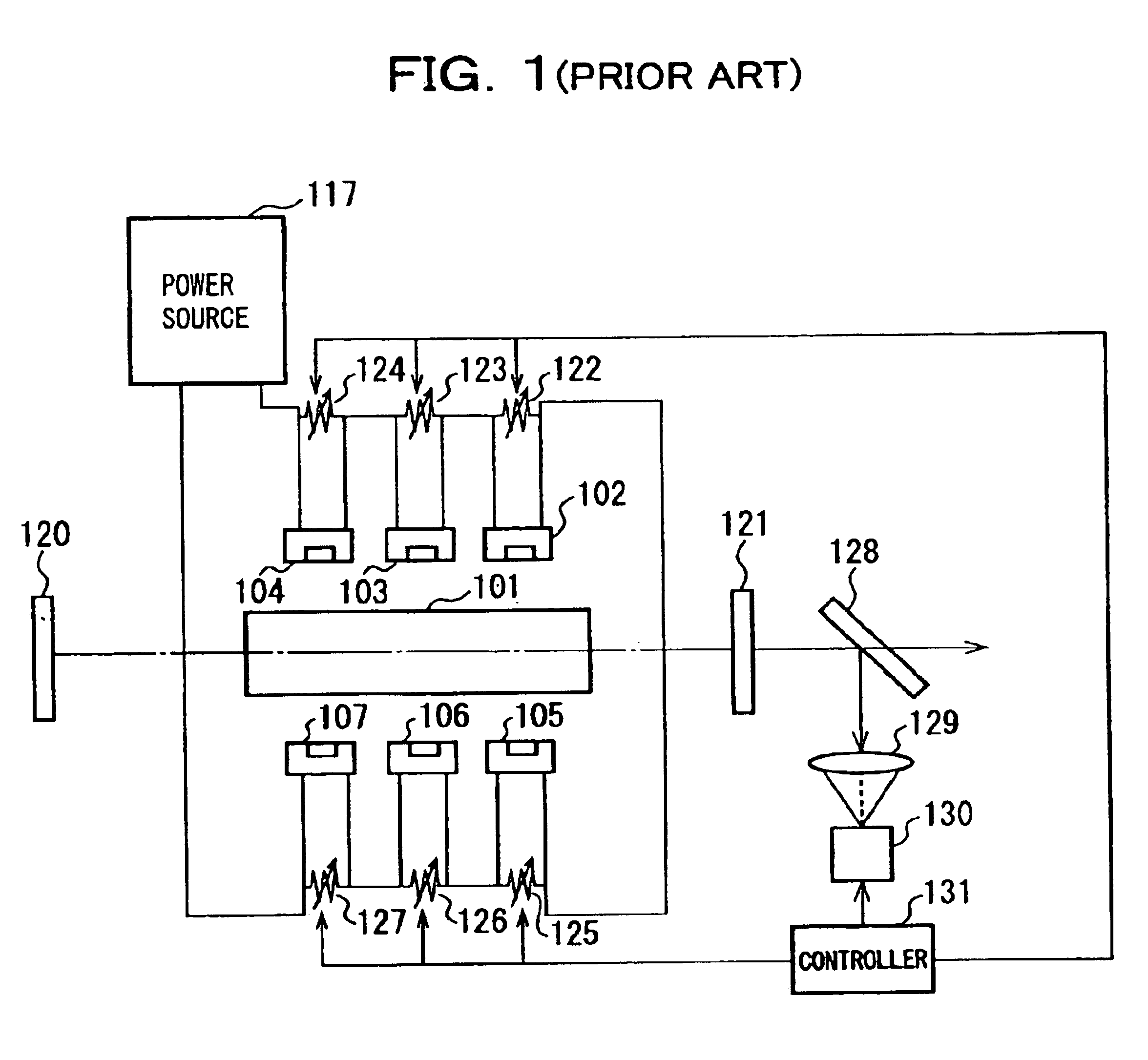
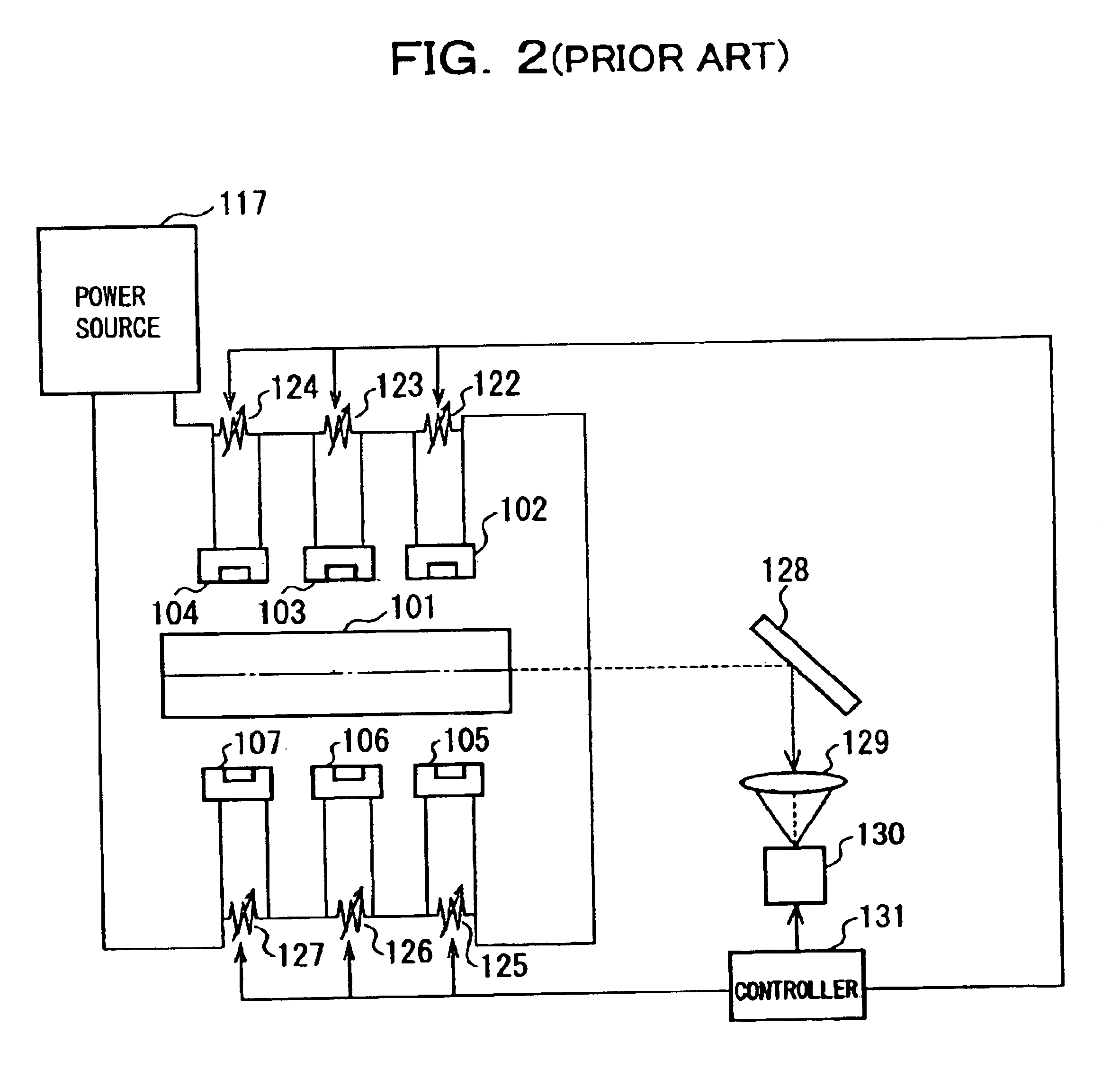
Further, in the conventional methods shown in FIGS. 1 and 2, since the CCD camera needs to be installed along the laser optical axis or on its extension and the fluorescence distribution cannot be observed due to an intense laser beam when the laser is oscillated, the resonator mirror needs to be removed once during measurement of the fluorescence distribution or the mirror is temporarily inserted in the resonator to keep the solid-state laser apparatus from oscillating, which is not practical because the LD degradation cannot be detected during operation.
In addition, when a plurality of laser rods are arranged in the laser apparatus in order to obtain high laser output, it is extremely difficult for one CCD camera to observe the fluorescence distribution in a long laser rod or a plurality of laser rods at once from one direction along the laser oscillation optical axis due to a focal distance of imaging and the like.
For this reason, a plurality of CCD's, a plurality of mirrors, imaging lenses with various focal distances and the like are required, and thus an optical system becomes very complicate and its cost becomes high.
Furthermore, one power source deals with a large current and a high voltage, a cooling method of the electronic parts, reduction of durability and reliability, and difficulty of replacement and maintenance due to large size of each part are large problems practically.
In addition, when the variable resistors control the drive current for each LD, problems such as heating and drift in the resistor and reduction of operation efficiency also occur.
On the other hand, the mechanism for controlling the drive current for each LD does not function effectively since time fluctuation and thermal fluctuation of the current value supplied from the power source to each LD, ripple, and a fluctuation amount of fluorescence affected by detection fluctuation of a detector or noise are larger.
Moreover, a problem caused when all LD's are driven by one power source is that all LD's are broken simultaneously in a same manner if an excessive current exceeding an allowable range of the LD flows by a defective part in the power source, malfunction of a control system, an operation error by an operator, and an external factor such as thunderbolt and power out.
When the photo-detector is directly adjacent to a laser oscillation optical path in the laser resonator, there are cases where it cannot be made closer due to the shape and the size of the photo-detector or an installation position is limited.
Because of the weak directivity of the fluorescence, the fluorescence spreads quickly when it is propagated in space to the photo-detector installed at a remote position from the laser oscillation optical path, and there are cases where sufficient light quantity for detection cannot be obtained.
Then, when output of the photo-detector saturates or gain of a signal amplifier is reduced to avoid saturation, there are cases where the fluorescence intensity before oscillation cannot be measured accurately.
Further, when the oscillation light made incident into the photo-detector is very intense, it might break the photo-detector itself or deteriorates its performance.

Method used


Image

  • Laser-diode-pumped solid-state laser apparatus and status diagnostic method of the same
  • Laser-diode-pumped solid-state laser apparatus and status diagnostic method of the same
  • Laser-diode-pumped solid-state laser apparatus and status diagnostic method of the same

Examples


Embodiment Construction

In a preferred embodiment according to the present invention, the laser-diode-pumped solid-state laser apparatus has at least: a laser rod; a laser diode device that generates pumping light; a reflection mirror provided at a position near the laser optical axis in the laser resonator and not blocking the optical axis; optical unit such as an optical waveguide medium; and a photo-detector that detects fluorescence, in which the photo-detector detects the quantity of the fluorescence generated from the solid-state laser medium, and the degradation status of the laser diode light source is constantly diagnosed by comparing the fluorescence quantity with a predetermined value or a previously measured value.

The embodiments of the foregoing present invention will be described in more detail with reference to the drawings.

First, description will be made for the laser-diode-pumped solid-state laser apparatus according to the first embodiment of the present invention referring to FIG. 3. FIG...


PUM


Abstract

A laser-diode-pumped solid-state laser apparatus includes a laser rod, and laser diode devices that generate pumping light. Optical unit such as a reflection mirror and an optical waveguide medium is provided at a position in a laser resonator near a laser optical axis and not blocking the optical axis. A photo-detector detects a quantity of fluorescence generated from solid-state laser medium. The fluorescence quantity is compared with a predetermined value or a previously measured value. Thus degradation status of a laser diode light source is constantly diagnosed.

Description

1. Technical Field of the InventionThe present invention relates to a laser-diode-pumped solid-state laser apparatus and a status diagnostic method of the apparatus. Particularly, the present invention relates to a highly reliable laser-diode-pumped solid-state laser apparatus and a status diagnostic method of the apparatus, which are capable of performing degradation diagnosis for a laser diode simply and easily.2. Description of the Related ArtA so-called LD (laser diode) pumped solid-state laser, which has a laser diode (hereinafter, abbreviated as LD) with higher absorption efficiency to a laser medium than a lamp and is small, highly efficient and has a long lifetime as a pumping light source, has drawn attention in recent years as a method of pumping light from a solid-state laser medium such as an Nd:YAG. Particularly, an LD-pumped solid-state laser apparatus has been developed in recent years, which emits a laser output reaching a kilowatt by using a few hundred LD's in one ...

Claims


Application Information

Patent Timeline
Patent Type & Authority Patents(United States)
IPC IPC(8): H01S3/0941H01S3/00H01S3/094H01S3/131
CPCH01S3/0941H01S3/1312H01S3/0014H01S3/0805H01S2301/02H01S3/09408
Inventor TSUNEKANE, MASAKIMUKAIHARA, KATSUJI
Owner LASERFRONT TECH
Why Eureka
Try Eureka