Vehicular air conditioning control apparatus

a control apparatus and air conditioning technology, applied in the direction of cooling fluid circulation, domestic cooling apparatus, lighting and heating apparatus, etc., can solve the problems of deficiency of the function of cooling a condenser by running wind and acceleration of fuel efficiency

Inactive Publication Date: 2004-11-30
CALSONIC KANSEI CORP +1
View PDF10 Cites 18 Cited by
  • Summary
  • Abstract
  • Description
  • Claims
  • Application Information

AI Technical Summary

Problems solved by technology

Therefore, when the cooling fan is controlled similarly under all of the vehicular conditions, there poses a problem that a deterioration in fuel efficiency is accelerated under specific vehicle conditions (in cooling down and in idling).
Further, in the idling, a function of cooling a condenser by running wind becomes deficient.

Method used


Image

  • Vehicular air conditioning control apparatus
  • Vehicular air conditioning control apparatus
  • Vehicular air conditioning control apparatus

Examples


Embodiment Construction

)

First, a structure of the preferred embodiment will be explained.

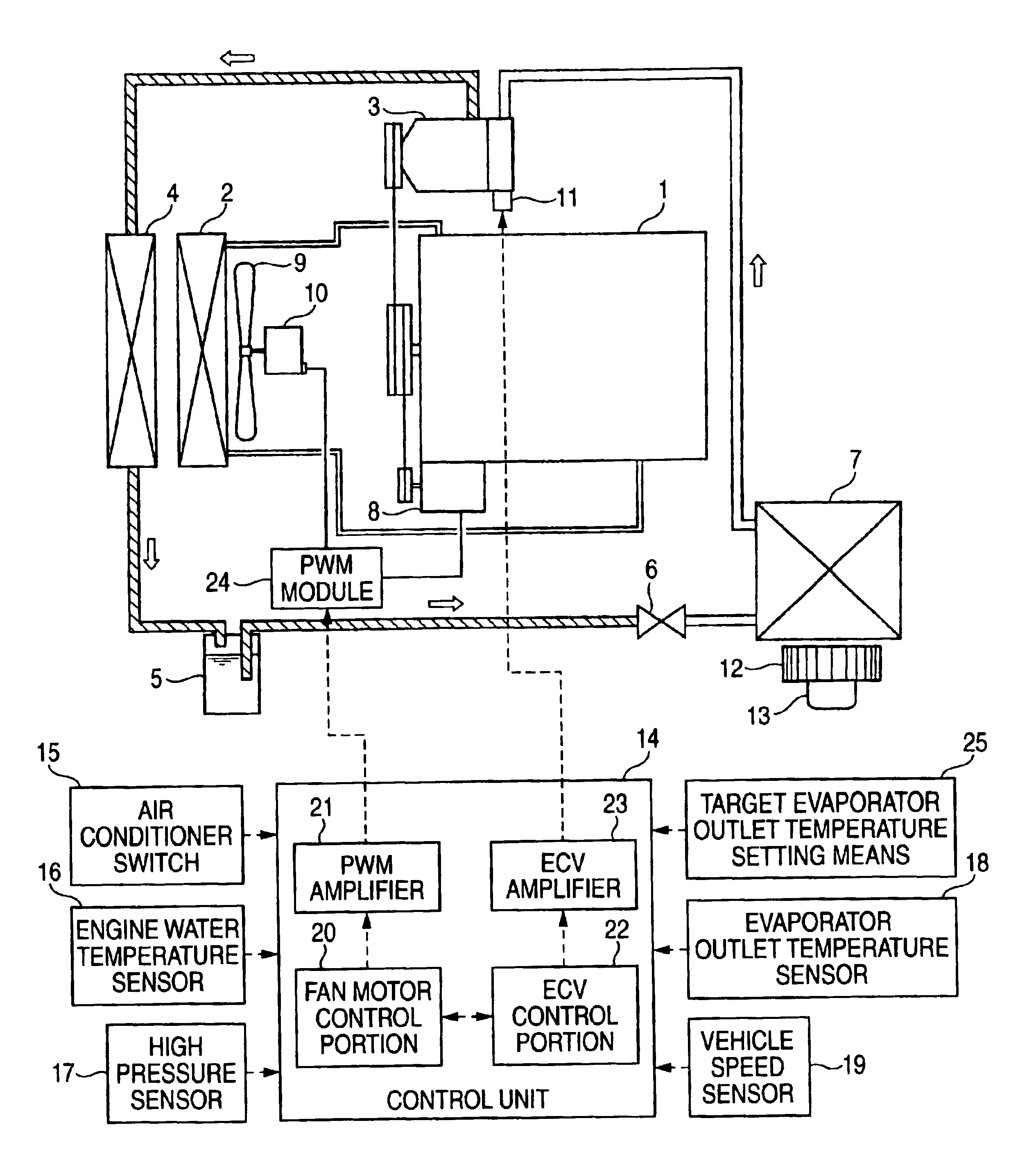
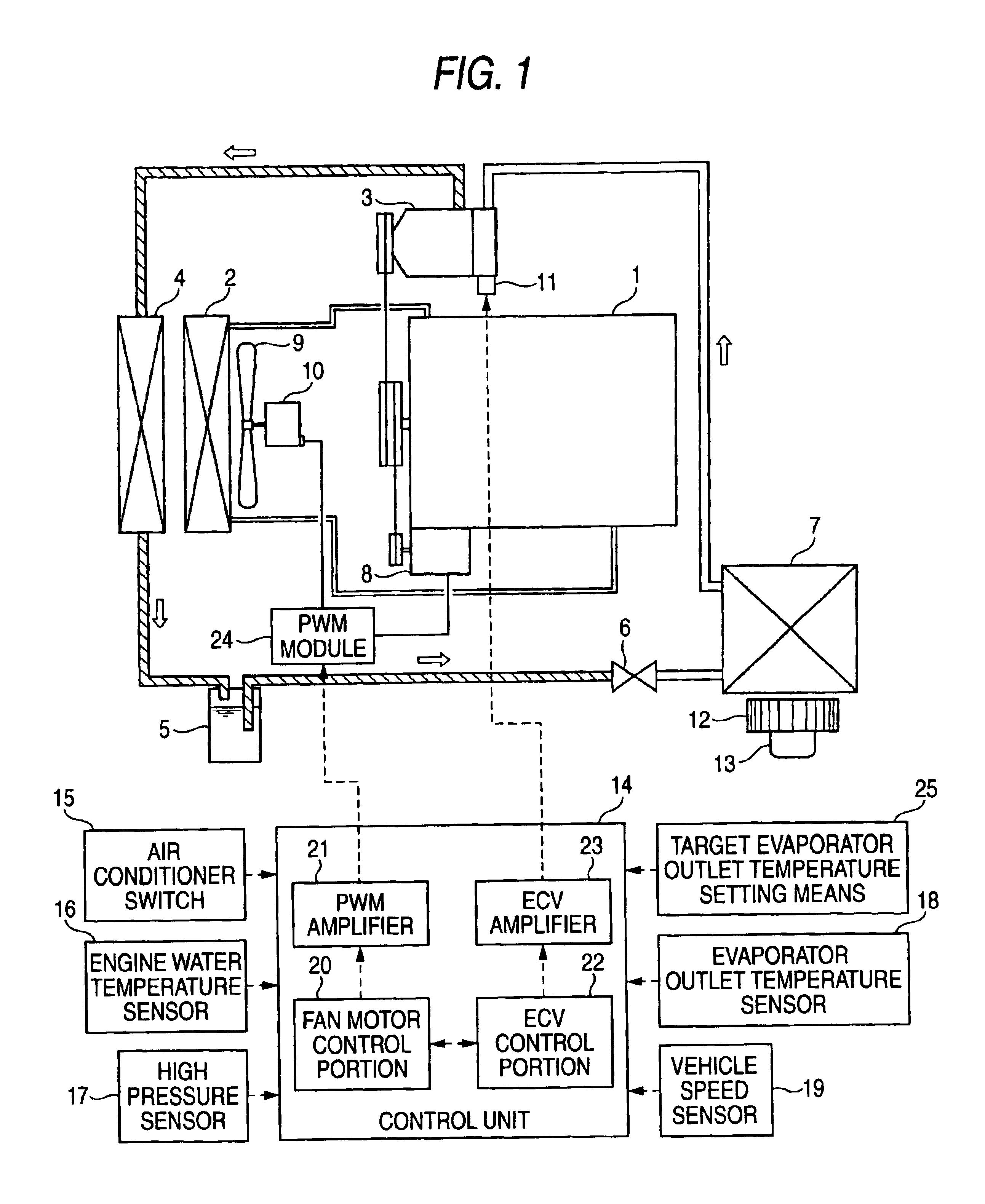
FIG. 1 is a total system view showing a vehicular air conditioning control apparatus according to the embodiment. In FIG. 1, numeral 1 designates an engine, numeral 2 designates a radiator, numeral 3 designates an external (variable capacity) control type compressor (compressor), numeral 4 designates a condenser, numeral 5 designates a liquid tank, numeral 6 designates a thermostatic expansion valve, numeral 7 designates an evaporator, numeral 8 designates an alternator, numeral 9 designates an electric cooling fan, numeral 10 designates a fan motor, numeral 11 designates a control valve, numeral 12 designates a blower fan and numeral 13 designates a blower fan motor.

The engine 1 and the radiator 2 are connected by an engine cooling water inlet pipe and an engine cooling water outlet pipe.

An air conditioning cycle in the apparatus of the embodiment is constituted by the external control type compressor 3, the condense...


PUM


Abstract

In a vehicular air conditioning control apparatus having a compressor and an electric cooling fan of an externally controlled type, a fan motor control for increasing fan motor load is carried out in a compressor discharge capacity region lower than in normal control in below-listed cases.(1) When a requested cooling performance is predicted to increase.(2) When a vehicle is brought into an idling state.(3) In cool down in which a requested cooling performance is predicted to increase to be equal to or larger than a set value, or when a vehicle is brought into an idling state.

Description

The present disclosure relates to the subject matter contained in Japanese Patent Application No. 2002-140935 filed on May 16, 2002, which is incorporated herein by reference in its entirety.1. Field of the InventionThe present invention relates to a technical field of a vehicular air conditioning control apparatus adopting an electric cooling fan of an external (variable capacity) control type in an air conditioning cycle.2. Description of the Related ArtConventionally, there is known a vehicular air conditioning control apparatus, as such described in JP-A-2000-274243.In the publication, with an object of achieving necessary minimum operation of a cooling fan over an entire operating region, there is described an apparatus for controlling an electric cooling fan arranged on the back side of a condenser and a radiator by constituting reference parameters by vehicle speed, engine cooling water temperature and compressor discharge pressure and selecting a control constant from a cool...

Claims


Application Information

Patent Timeline
Patent Type & Authority Patents(United States)
IPC IPC(8): B60H1/32
CPCB60H1/3205B60H1/3208F25B2600/111B60H2001/3266B60H2001/3277B60H2001/325
Inventor HIROSE, RYUICHINADAMOTO, HIROYASUMASUKO, KAZUOUCHIYAMA, HAJIME
Owner CALSONIC KANSEI CORP
Why Eureka
Try Eureka