AI technical title is built by Patsnap AI team. It summarizes the technical point description of the patent document.
a zoom lens and wide angle technology, applied in the field of wide angle, can solve the problems of high zoom lens ratio, little known, etc., and achieve the effects of high image-formation capability, improved results, and effective use of image quality
Inactive Publication Date: 2004-11-30
OM DIGITAL SOLUTIONS CORP
View PDF11 Cites 13 Cited by
Summary
Abstract
Description
Claims
Application Information
AI Technical Summary
This helps you quickly interpret patents by identifying the three key elements:
Problems solved by technology
Method used
Benefits of technology
Benefits of technology
The present invention provides a wide-angle, high-zoom-ratio zoom lens system that is compatible with various camera formats, including digital cameras. The lens system has a fast aperture and is designed to have a high zoom ratio and a wide field of view at the wide-angle end. It is also designed to have a high-speed autofocus system and is compatible with TTL optical finders. The lens system is suitable for high-end users who require high-quality image-pickup capabilities and fast performance. The first lens group is movable and has positive refracting power, while the second lens group moves toward the image side and has negative refracting power. The rear lens group has at least two movable subgroups or has at least two spacings variable during zooming. The lens system has a wide-angle field of view at the wide-angle end and a fast aperture for both still and video cameras.
Problems solved by technology
However, wide-angle, high-zoom-ratio zoom lenses, which are well suitable for image-pickup formats considerably smaller in size than the film camera formats and are fast as expressed by an F-number of about 2.0 to 2.8 at the wide-angle end, are little known except those for TV cameras and other commercial purposes.
Method used
Image
Click on the blue label to locate the original text in one second.
Reading with bidirectional positioning of images and text.
Examples
example 1
Aspherical Coefficients
9 th surface
K=0
A.sub.4 =2.1263.times.10.sup.-5
A.sub.6 =1.5727.times.10.sup.-8
A.sub.8 =3.9610.times.10.sup.-11
A.sub.10 =0.0000
18 th surface
K=0
A.sub.4 =-1.9875.times.10.sup.-5
A.sub.6 =-1.3029.times.10.sup.-8
A.sub.8 =5.1888.times.10.sup.-11
A.sub.10 =0.0000
26 th surface
K=0
A.sub.4 =-1.7061.times.10.sup.-5
A.sub.6 =-8.7539.times.10.sup.-9
A.sub.8 =1.1345.times.10.sup.-10
A.sub.10 =0.0000
Zooming Data (.infin.)
example 2
Aspherical Coefficients
11 th surface
K=0
A.sub.4 =-2.3956.times.10.sup.-5
A.sub.6 =1.1363.times.10.sup.-8
A.sub.8 =-2.9304.times.10.sup.-11
A.sub.10 =0.0000
18 th surface
K=0
A.sub.4 =-1.9310.times.10.sup.-5
A.sub.6 =-5.6603.times.10.sup.-9
A.sub.8 =-5.6829.times.10.sup.-11
A.sub.10 =0.0000
26 th surface
K=0
A.sub.4 =-1.9084.times.10.sup.-5
A.sub.6 =8.1108.times.10.sup.-9
A.sub.8 =2.2527.times.10.sup.-10
A.sub.10 =0.0000
Zooming Data (.infin.)
example 3
Aspherical Coefficients
13 th surface
K=0
A.sub.4 =-1.4437.times.10.sup.-5
A.sub.6 =2.9795.times.10.sup.-9
A.sub.8 =-9.7997.times.10.sup.-12
A.sub.10 =0.0000
19 th surface
K=0
A.sub.4 -1.9829.times.10.sup.-5
A.sub.6 =-1.2490.times.10.sup.-9
A.sub.8 =9.5912.times.10.sup.-12
A.sub.10 =0.0000
28 th surface
K=0
A.sub.4 =-8.0968.times.10.sup.-6
A.sub.6 =-1.4115.times.10.sup.-8
A.sub.8 =-3.7788.times.10.sup.-10
A.sub.10 =0.0000
Zooming Data (.infin.)
PUM
Abstract
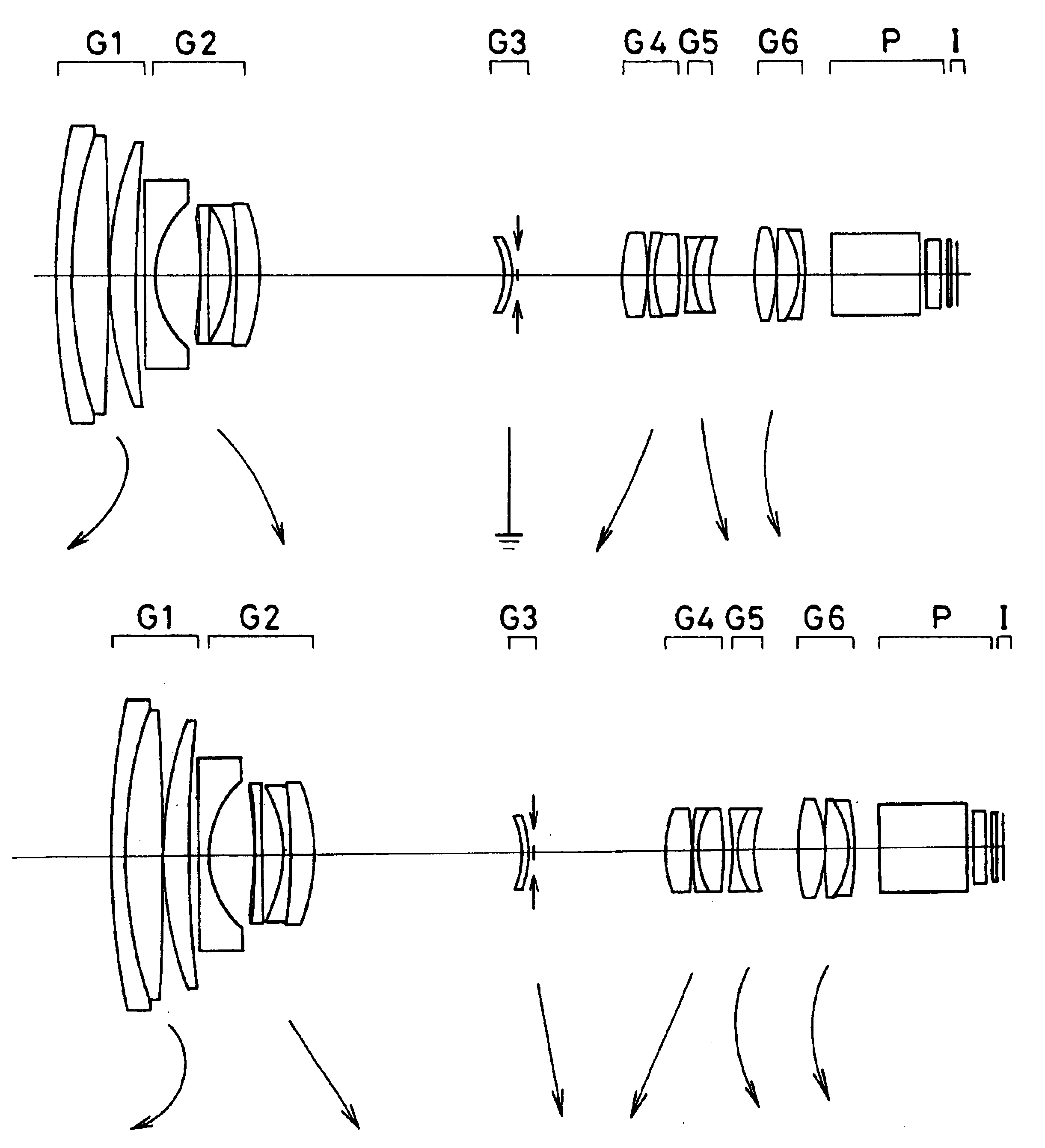
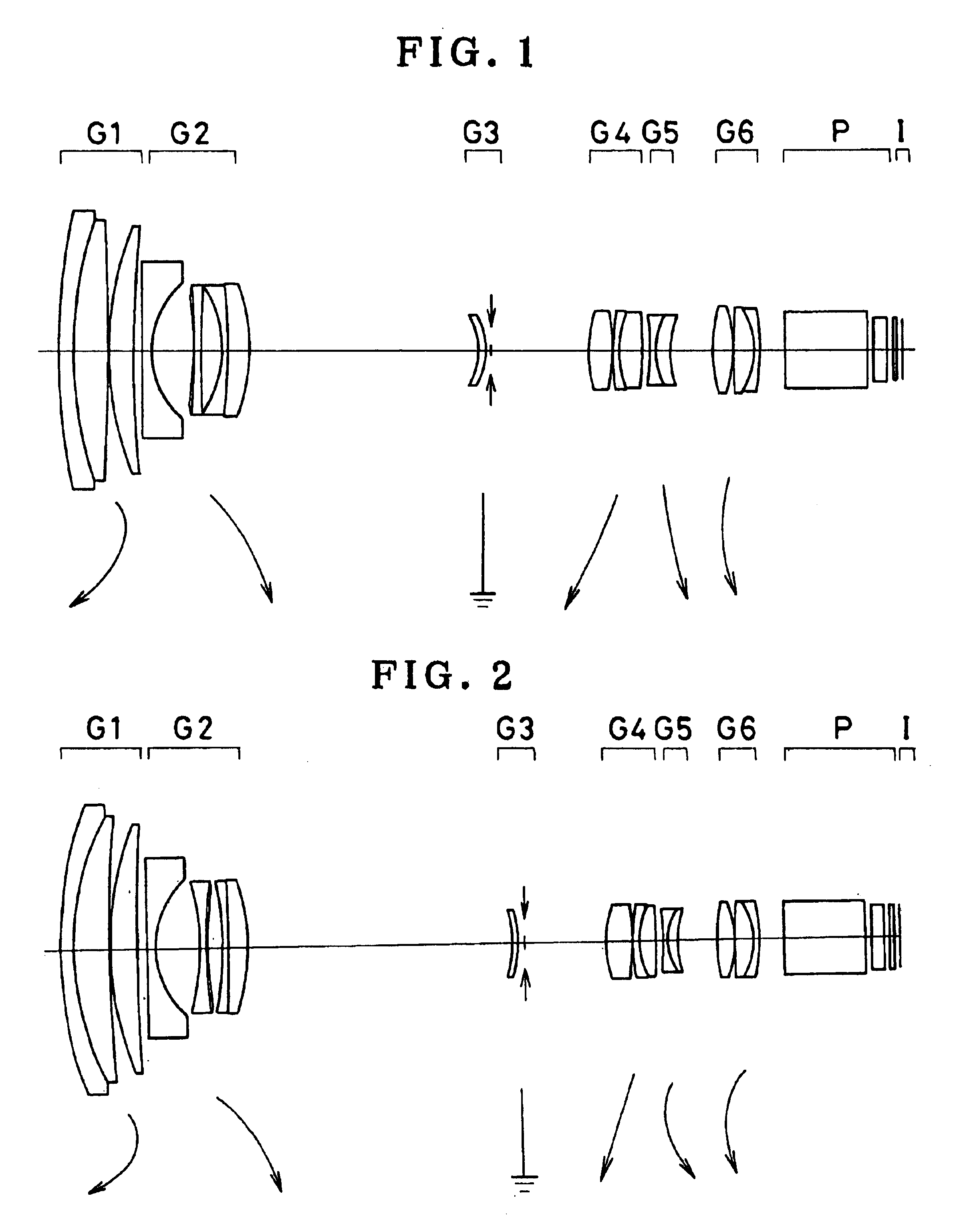
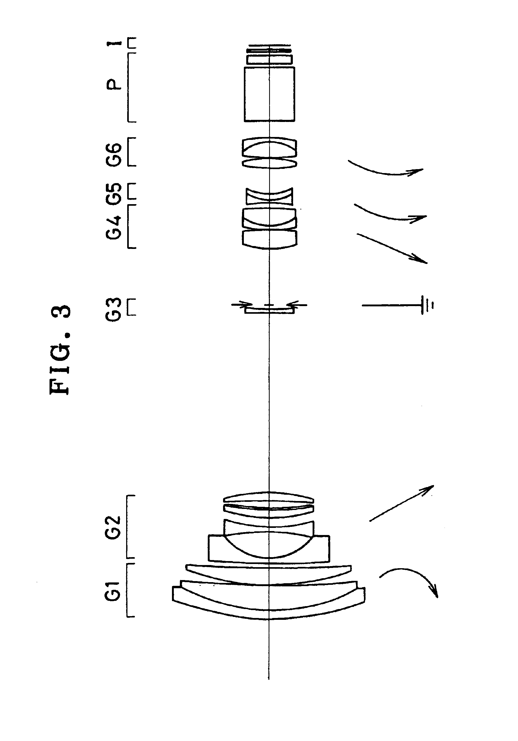
The invention relates to a zoom lens system which is compatible with a TTL optical finder having a diagonalfield angle of at least 70° at the wide-angle end and about 7 to 10 magnifications and is fast as represented by an F-number of about 2.8 at the wide-angle end. The zoom lens system comprises a first lens group G1 which is movable along its optical axis during zooming and has positive refracting power, a second lens group G2 which moves toward the image side along the optical axis during zooming from the wide-angle end to the telephoto end and has negative refracting power and rear lens groups G3 to G6 having at least two spacings variable during zooming. In particular, the focal length f1 of the first lens group G1 should meet 6<F1 / L<20 where L is the diagonal length of an effective image pickup surface I located in the vicinity of an image-formation plane.
Description
The present invention relates generally to a zoom lens, and more particularly to a high-aperture-ratio, high zoom-ratio zoom lenssystem including a wide-angle zone which has a phototaking field angle of at least 70.degree. suitable for cameras in general, and video cameras or digital cameras in particular.In recent years, attention has been paid on digital cameras (electronic cameras) which are potential next-generation cameras superseding silver-salt 135 mm film (usually called Leica size) cameras. For digital cameras for general users, single-focus lenses having a diagonalfield angle of about 60.degree. or zoom lenses of about 3 magnifications using the same at wide-angle ends go mainstream. For high-class users, on the other hand, zoom lenses must be further extended to the wide-angle or telephoto end, and be compatible with TTL optical finders as well. As a matter of course, such zoom lenses are required to have ever higher performance. For zoom lenses having a diagonal field ...
Claims
Application Information
Patent Timeline
Application Date:The date an application was filed.
Publication Date:The date a patent or application was officially published.
First Publication Date:The earliest publication date of a patent with the same application number.
Issue Date:Publication date of the patent grant document.
PCT Entry Date:The Entry date of PCT National Phase.
Estimated Expiry Date:The statutory expiry date of a patent right according to the Patent Law, and it is the longest term of protection that the patent right can achieve without the termination of the patent right due to other reasons(Term extension factor has been taken into account ).
Invalid Date:Actual expiry date is based on effective date or publication date of legal transaction data of invalid patent.

