Measuring tool, encoder and producing method of encoder
a technology of encoder and measuring tool, which is applied in the direction of mechanical measuring arrangement, instruments, applications, etc., can solve the problems of increased production cost, complex production line, and increased time and cost for machining metal down into desired shap
- Summary
- Abstract
- Description
- Claims
- Application Information
AI Technical Summary
Problems solved by technology
Method used
Image
Examples
first embodiment
[First Embodiment]
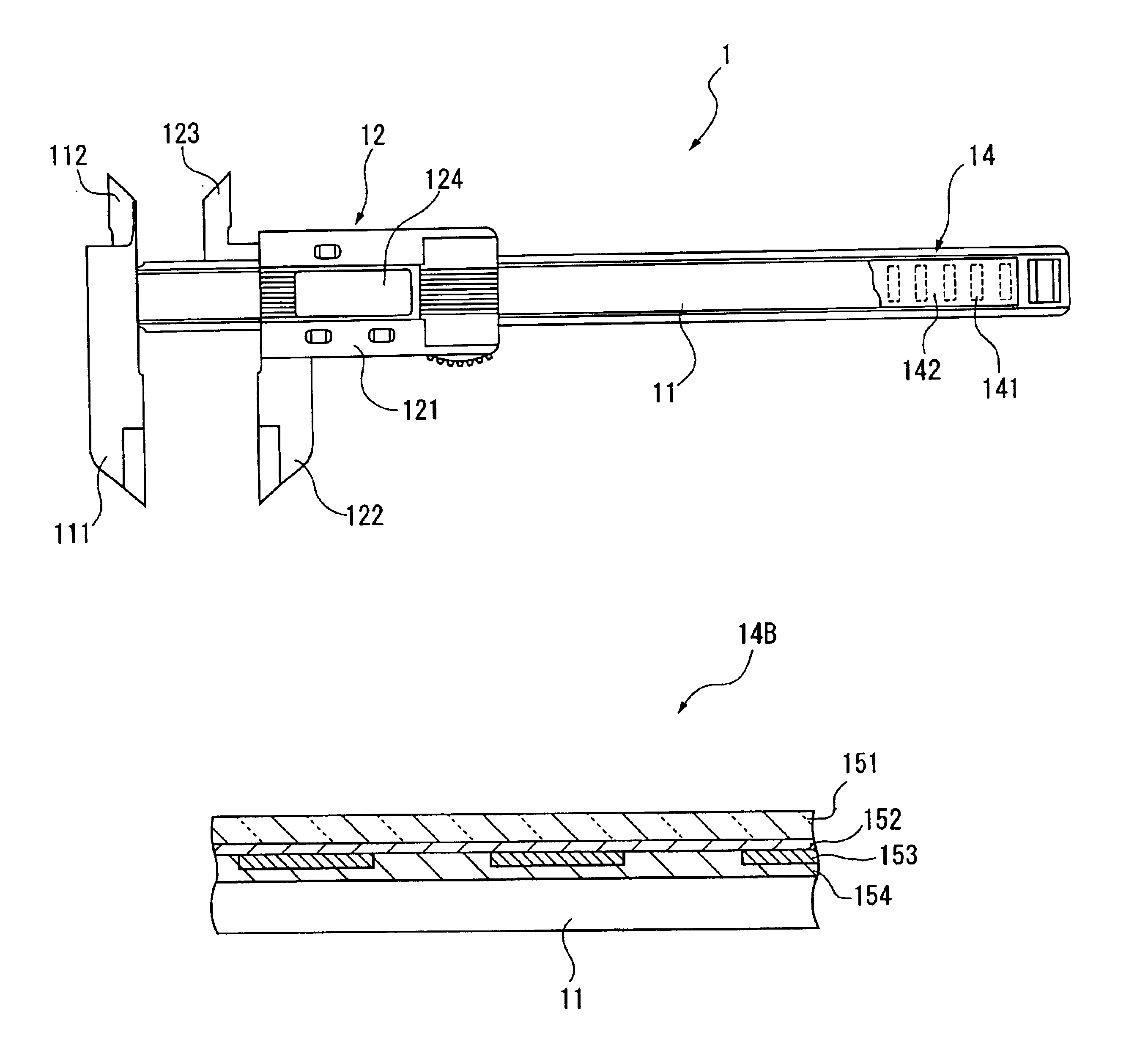
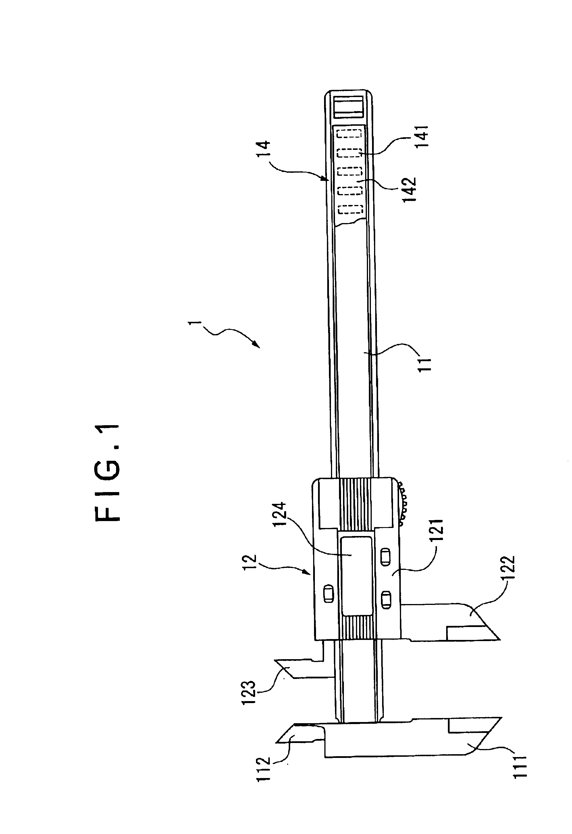
FIG. 1 shows a digital caliper gauge 1 having an encoder according to a first embodiment of the present invention.
The caliper gauge 1 has a longitudinal main beam 11 as a base, and a slider 12 as a movable component (slide body) slidable along the longitudinal direction of the main beam 11.
The main beam has an outside-measuring jaw 111 and an inside-measuring jaw 112 provided on a longitudinal end of the main beam 11 and a main scale 14 of an electrostatic encoder provided along the longitudinal direction of the main beam 11.
The main beam 11 is molded integrally with the outside-measuring jaw 111 and the inside-measuring jaw 112 by injection molding of synthetic resin by polystyrene containing carbon nanofiber as a nanoscale compound.
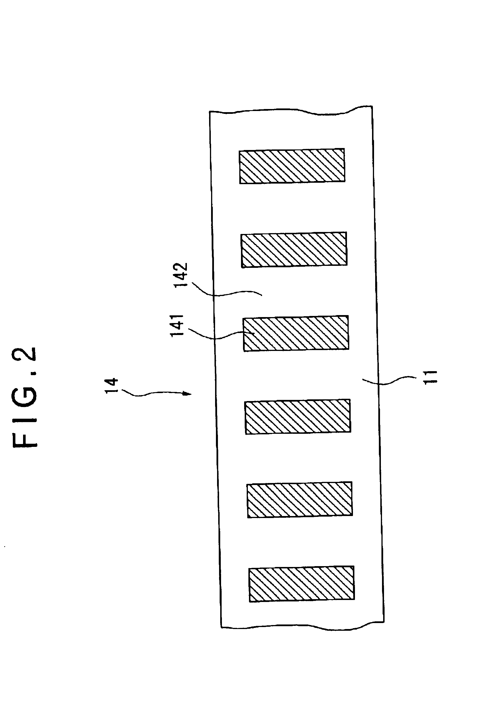
As shown in enlarged illustration of FIG. 2, the main scale 14 is an electrode pattern consisting of an electro-conductive portion 141 as an electrode formed along the longitudinal direction of the main beam 11 at a predetermined pitch...
second embodiment
[Second Embodiment]
FIG. 4 shows a dial gauge 2 as a second embodiment of measuring tool according to the present invention. FIG. 4 is an illustration of the dial gauge 2 with back lid thereof being detached. Though a dial gauge is taken as an example in the present embodiment, a micrometer may also be constructed in the same manner.
The dial gauge 2 has a case body 21, a spindle 22 as a slide body penetrating the outer circumference of the case body 21 and being slidably supported in the axial direction thereof, a power transmitting portion 23 for transmitting the displacement of the spindle 22 as a power and a non-illustrated display for displaying the transmitted power as a displacement amount of the spindle 2.
The case body 21 has a bushing 211A as a slide guide for slidably guiding the spindle 22 in the axial direction and a stem 212 protruding downward in FIG. 4. An engaging groove 213 is formed along slide direction of the spindle 22 on the inner circumference thereof. Another b...
third embodiment
[Third Embodiment]
FIG. 6 shows a linear encoder 3 used for movement amount measuring tool according to the present invention. FIG. 6 is a cross section of the linear encoder 3.
The linear encoder 3 has a frame 31 as a base, a scale 32 provided on the frame 31, a slide 33 as a slide body capable of slide movement relative to the frame 31, a detector 34 moving together with the slide 33 to detect the movement relative to the scale 32, a roller slider 35 as a slide guide provided on the slide 33 for guiding the slide movement of the slide 33 while being in contact with the frame 31 and the scale 32. In FIG. 6, the slide direction of the slide 33 is perpendicular to the surface of FIG. 6. FIG. 7 shows a side elevational view of the slide 33.
The frame 31, the slide 33 and the slider 35 are formed by injection-molding of the synthetic resin containing carbon nanofiber. The slider 35 is formed by injection-molding of the synthetic resin containing carbon nanofiber and has electro-conductivi...
PUM
 Abstract
Description
Claims
Application Information
 - R&D
- Intellectual Property
- Life Sciences
- Materials
- Tech Scout
- Unparalleled Data Quality
- Higher Quality Content
- 60% Fewer Hallucinations
Browse by: Latest US Patents, China's latest patents, Technical Efficacy Thesaurus, Application Domain, Technology Topic, Popular Technical Reports.
© 2025 PatSnap. All rights reserved.Legal|Privacy policy|Modern Slavery Act Transparency Statement|Sitemap|About US| Contact US: help@patsnap.com


