Filtration media for filtering particulate material from gas streams

a technology of air filtration media and gas stream, which is applied in the direction of filtration separation, separation process, other domestic articles, etc., can solve the problems of charge dissipation, current limitations, and loss of filtration efficiency in use of air filter media and media manufactured by wet-laying process,

Inactive Publication Date: 2006-06-29
EI DU PONT DE NEMOURS & CO
View PDF32 Cites 157 Cited by
  • Summary
  • Abstract
  • Description
  • Claims
  • Application Information

AI Technical Summary

Problems solved by technology

Electrostatically enhanced air filter media and media manufactured by the wet laid process, more specifically with the use of glass fibers, currently have limitations.
Electrostatically treated meltblown filter media, as described in U.S. Pat. Nos. 4,874,659 and 4,178,157, perform well initially, but quickly lose filtration efficiency in use due to dust loading as the media begin to capture particles and the electrostatic charge thus becomes insulated.
In addition, as the effective capture of particulates is based on the electrical charge, the performance of such filters is greatly influenced by air humidity, causing charge dissipation.
Microglass fibers and blends containing microglass fibers are typically relatively brittle and can break when pleated, and produce undesirable yield losses.
Broken microglass fibers can also be released into the air by filters containing microglass fibers, creating a potential health hazard if the microglass were to be inhaled.

Method used


Image

  • Filtration media for filtering particulate material from gas streams

Examples


example 1

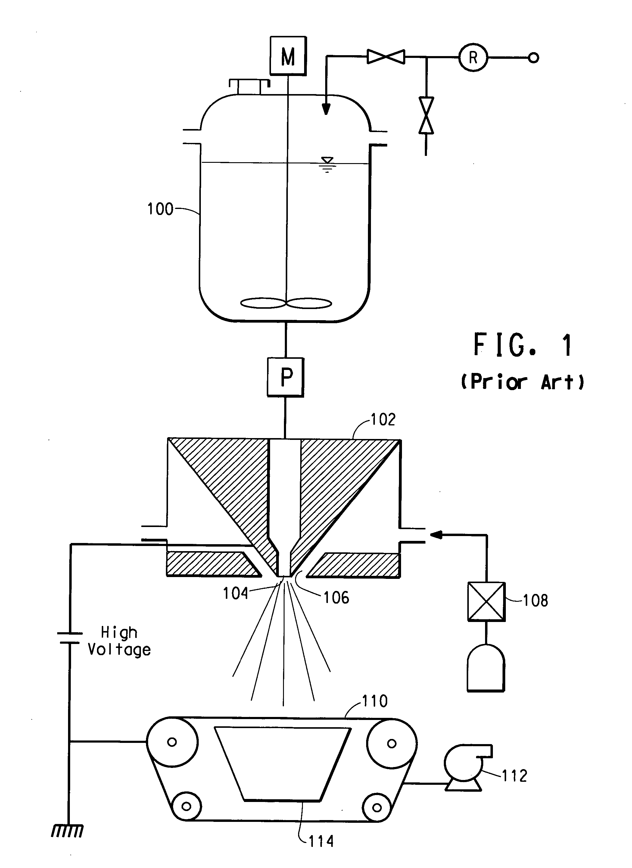
[0036] Nanofiber layers were made by electroblowing a solution of nylon 6,6 polymer having a density of 1.14 g / cc (available from E. I. du Pont de Nemours and Company, Wilmington, Del.) at 24 weight percent in formic acid at 99% purity (available from Kemira Oyj, Helsinki, Finland). The polymer and solvent were fed into a solution mix tank, the solution transferred into a reservoir and metered through a gear pump to an electroblowing spin pack having spinning nozzles, as described in PCT Patent Publication No. WO 03 / 080905. The spin pack was 0.75 meter wide and had 76 spinning nozzles. The pack was at room temperature with the pressure of the solution in the spinning nozzles at 10 bar. The spinneret was electrically insulated and applied with a voltage of 75 kV. Compressed air at a temperature of 44° C. was injected through air nozzles into the spin pack at a rate of 7.5 m3 / minute and a pressure of 660 mm H2O. The solution exited the spinning nozzles into air at atmospheric pressure...

example 2

[0038] An SN structure was made as described in Example 1, but at a higher basis weight of the nanofiber layer. The resulting structure was challenged at various particle sizes for filtration efficiency, and the results are given in Table 1.

TABLE 1NanofiberNanofiberbasisPressureFrazier airdiameterweightEfficiencyDroppermeabilityEx. No.(nm)*(g / m2)(%)(mm H2O)(m3 / m2 / min)1341 / 387369.93.7372374 / 3625856.422

*first measurement / second measurement

example 3

[0039] A filtration medium having an SNS structure was formed by hand consisting a nanofiber layer having a basis weight of about 3 g / m2 sandwiched between two spunbond layers each having a basis weight of about 21 g / m2 made from bicomponent sheath-core fibers having a sheath of polyethylene (PE) and a core of poly(ethylene terephthalate) (PET). The average diameter of the nanofibers was about 651 nm. The nanofibers were nylon. The Frazier air permeability, the pressure drop and the efficiency of the filtration medium are listed in Table 2.


PUM

PropertyMeasurementUnit
diameteraaaaaaaaaa
diameteraaaaaaaaaa
thicknessaaaaaaaaaa

Abstract

A filtration medium is disclosed for use in air filters used in heating, ventilating and air conditioning systems. The medium contains at least one nanofiber layer of fibers having diameters less than 1 μm and at least one carrier layer, each nanofiber layer having a basis weight of at least about 2.5 g / m2, and up to about 25 g / m2. The medium has sufficient stiffness to be formed into a pleated configuration.

Description

BACKGROUND OF THE INVENTION [0001] 1. Field of the Invention [0002] The present invention relates to air filtration media, for filtering particulate material from gas streams. [0003] 2. Description of the Related Art [0004] Filter media typically utilized for HVAC air filters that perform at efficiencies less than 99.97% at a 0.3 micron challenge are either glass, cellulose or polymer based. Filters made with media in this performance range are typically referred to as “ASHRAE filters” since the American Society of Heating, Refrigerating and Air-Conditioning Engineers writes standards for the performance of filter media in such applications. Polymer based filter media are typically spunbond or meltblown nonwovens that are often electrostatically enhanced to provide higher filtration efficiency at lower pressure drop when compared to glass or cellulose media manufactured by a wet laid paper-making process. [0005] Electrostatically enhanced air filter media and media manufactured by t...

Claims


Application Information

Patent Timeline
Patent Type & Authority Applications(United States)
IPC IPC(8): B01D46/00D04H3/16
CPCB01D39/1615D04H13/007B01D39/18B01D46/22B01D46/521B01D46/546B01D2239/0681B01D2239/10B01D2273/28B01D2275/10B32B5/022B32B5/024B32B5/26B32B2250/20B32B2262/0261B32B2307/544B32B2307/546B32B2459/00D04H3/16D04H13/002B01D39/163D04H13/00D04H1/4374D04H1/559D04H1/728B01D2239/025
Inventor BRYNER, MICHAEL ALLENJONES, DAVID CHARLESLIM, HYUN SUNGWISEMAN, B. LYNNEHOVANEC, JOSEPH BRIAN
Owner EI DU PONT DE NEMOURS & CO
Why Eureka
Try Eureka