Particle filter system incorporating nanofibers

a nanofiber and filter media technology, applied in the field of nanofibers, can solve the problems of inability to produce, difficult to handle, and the nanofibers of the electrolyte nanofibers smaller than 500 nm are typically fragile, and the conventional layered nanofiber filter made from nanofibers deposited on the conventional porous filter media have inherent limitations

Active Publication Date: 2008-05-15
RES TRIANGLE INST
View PDF26 Cites 159 Cited by
  • Summary
  • Abstract
  • Description
  • Claims
  • Application Information

AI Technical Summary

Benefits of technology

[0051]In one embodiment of the present invention, there is provided a filtration device including a filtration medium having a plurality of nanofibers of diameters less than 1 micron formed in

Problems solved by technology

However, electrospun nanofibers smaller than 500 nm are typically fragile, difficult to produce, and difficult to handle.
Conventional layered nanofiber filters made from nanofibers deposited on conventional porous filter media have inherent limitations.
Such a pliable substrat

Method used


Image

  • Particle filter system incorporating nanofibers
  • Particle filter system incorporating nanofibers
  • Particle filter system incorporating nanofibers

Examples


example 1

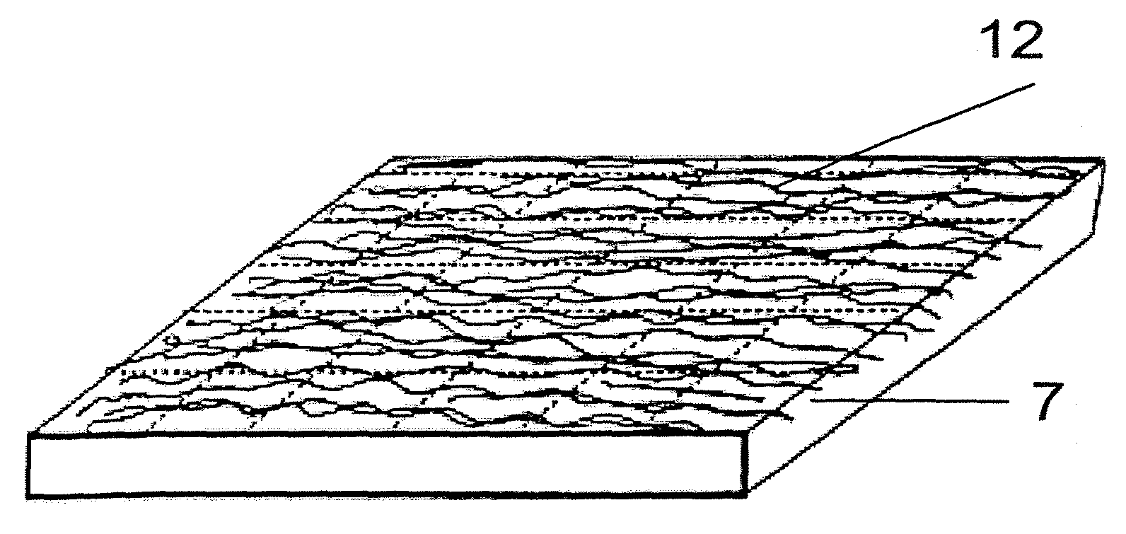
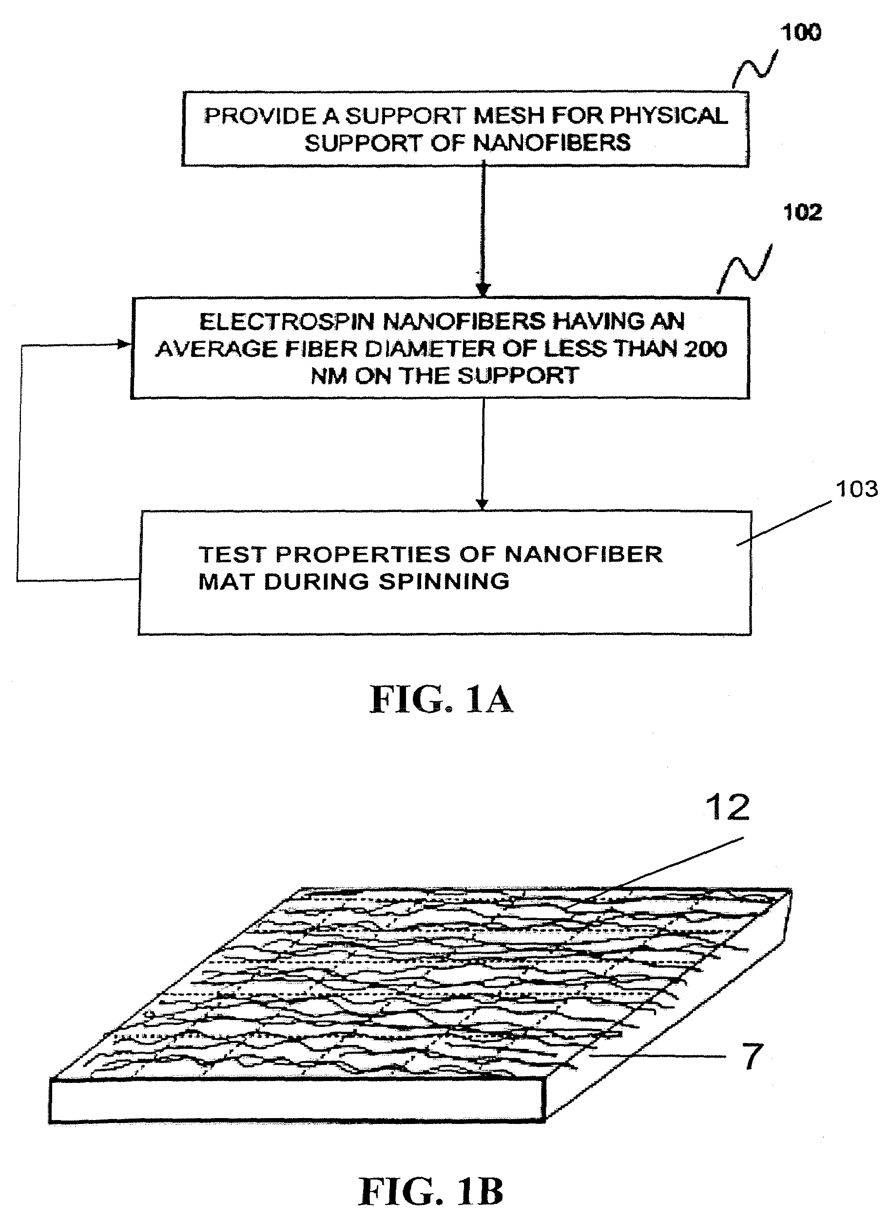
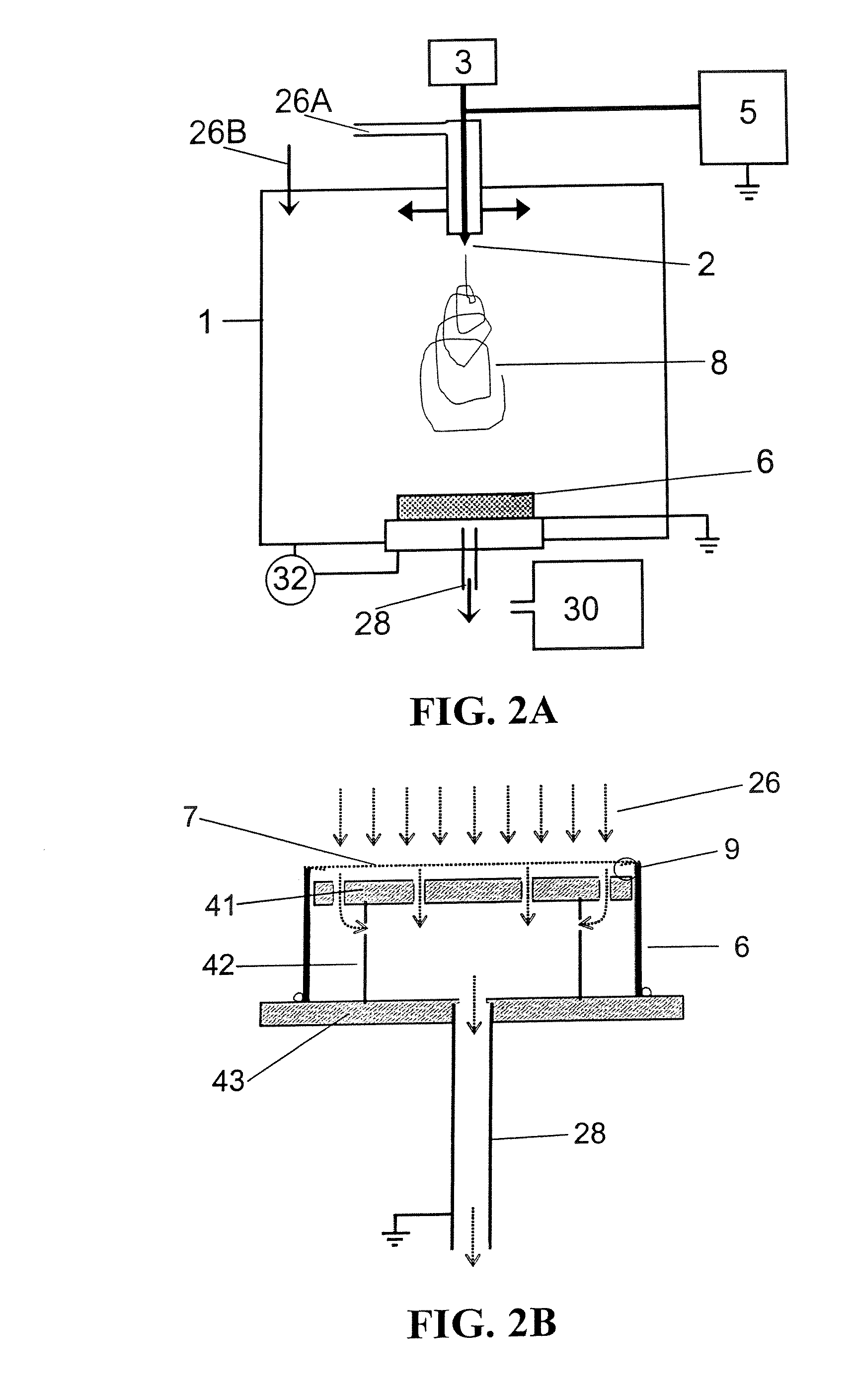
[0148]Standard aluminum window screen was cleaned with alcohol, rinsed with DI water, cleaned with acetone, rinsed with DI water, dried, and then cleaned with dilute (14 vol. %) sulfuric acid, thoroughly rinsed with DI water, and then dried with clean, dry nitrogen gas. An 8.89 cm diameter circle of the cleaned mesh was attached to a 7.7 cm long piece of 7.62 ID PVC pipe with some of the edges of the mesh folded under (9). The mesh was attached to the PVC frame with Locktite™ Epoxy gel. The mesh 7 frame 6 assembly was placed on the ground plate system 28, 41-43 inside the electrospinning enclosure 1. The distance between 7 and 41 was about 8 mm, the spark gap device 9 had a gap of about 5 mm. The side of 6 to outside edge of 43 was 7 mm (determines area of lower ground plate 43 that helps shape and maintain the electric field between emitter 2 and filter assembly). A mixture of dry and wetted (via bubbling through DI water) CO2 26 was used to obtain an RH in the range of 26 to 38%.

[...

example 2

[0151]The same aluminum mesh and filter frame configuration from Example 1 was used but a spark gap 9 of 3.5 mm was used with a mesh 7 to 41 distance of 5 mm. The RH was regulated to be in the range of 33 to 26%. The rest of the conditions and configurations were identical to Example 1. The filter was rotated 45° every 5 minutes for a total of 45 minutes to produce a filter with a pressure drop of 48.8 Pa and a penetration Pt of 1.7×10⁻⁵, that is a FoM of about 98 kPa−1.


PUM

PropertyMeasurementUnit
Lengthaaaaaaaaaa
Lengthaaaaaaaaaa
Fractionaaaaaaaaaa

Abstract

A filtration device including a filtration medium having a plurality of nanofibers of diameters less than 1 micron formed into a fiber mat in the presence of an abruptly varying electric field. The filtration device includes a support attached to the filtration medium and having openings for fluid flow therethrough. A device for making a filter material. The device includes an electrospinning element configured to electrospin a plurality of fibers from a tip of the electrospinning element, a collector opposed to the electrospinning element configured to collect electrospun fibers on a surface of the collector, and an electric field modulation device configured to abruptly vary an electric field at the collector at least once during electrospinning of the fibers. A method for making a filter material. The method provides a support having openings for fluid flow therethrough, electrospins nanofibers across an entirety of the openings, and abruptly varies an electric field at the collector at least once during electrospinning of the fibers.

Description

CROSS REFERENCE TO RELATED APPLICATIONS[0001]This application is related to U.S. application Ser. No. 10 / 819,916, filed on Apr. 8, 2004, entitled “Electrospinning of Polymer Nanofibers Using a Rotating Spray Head,” Attorney Docket No. 241015US-2025-2025-20, the entire contents of which are incorporated herein by reference. This application is also related to U.S. application Ser. No. 10 / 819,942, filed on Apr. 8, 2004, entitled “Electrospray / electrospinning Apparatus and Method,” Attorney Docket No. 241013US-2025-2025-20, the entire contents of which are incorporated herein by reference. This application is related to U.S. application Ser. No. 10 / 819,945, filed Apr. 8, 2004, entitled “Electrospinning in a Controlled Gaseous Envirornent,” Attorney Docket No. 245016US-2025-2025-20, the entire contents of which are incorporated herein by reference. This application is related to U.S. Ser. No. 11 / 130,269, filed May 17, 2005 entitled “Nanofiber Mats and Production Methods Thereof,” Attorn...

Claims


Application Information

Patent Timeline
IPC IPC(8): B01D39/14D04H1/00B29B13/00B03C3/00B05D5/12D04H1/728
CPCB01D39/1623B01D2239/025Y10S55/05D01D5/0092D01D5/0076Y10T442/622B03C3/155B05D1/06B05D1/14D01D5/00B82Y40/00B05D2210/00B01D35/06
Inventor ENSOR, DAVID S.WALLS, HOWARD J.ANDRADY, ANTHONY L.WALKER, TERI A.
Owner RES TRIANGLE INST
Why Eureka
Try Eureka