Ejector cycle

a technology of ejector cycle and evaporator, which is applied in the direction of refrigeration components, machine operation mode, light and heating apparatus, etc., can solve the problems of reducing the lubricating efficiency of the compressor, reducing the amount of lubricating oil returned to the compressor, and reducing the heat absorption performance of the evaporator

Inactive Publication Date: 2004-12-28
DENSO CORP
View PDF4 Cites 38 Cited by
  • Summary
  • Abstract
  • Description
  • Claims
  • Application Information

AI Technical Summary

Benefits of technology

It is an another object of the present invention to provide an ejector cycle that effectively reduces the size of a gas-liquid separator.
It is a further another object of the present invention to provide an ejector cycle that can reduces the lubrication oil staying in the low-pressure heat exchanger while reducing the size of the gas-liquid separator.
According to a first aspect of the present invention, an ejector cycle having an ejector includes a pipe member defining a refrigerant passage through which a refrigerant outlet side of a low-pressure heat exchanger is coupled to a refrigerant suction side of a compressor, and a switching means provided in the refrigerant passage to open and close the refrigerant passage. In the ejector cycle, when the switching means opens the refrigerant passage, at least refrigerant in the low-pressure heat exchanger is introduced to the refrigerant suction side of the compressor directly by the pumping operation of the compressor while bypassing the ejector. Accordingly, a lubrication oil amount staying in the low-pressure heat exchanger can be controlled equal to or smaller than a predetermined amount by introducing the refrigerant including the lubrication oil to the compressor through the refrigerant passage. Therefore, a sufficient amount of the lubrication oil can be returned to the compressor.
Further, the ejector cycle includes a gas-liquid separator for separating refrigerant from the ejector into gas refrigerant and liquid refrigerant, and the gas-liquid separator is disposed such that a gas refrigerant outlet of the gas-liquid separator is connected to the refrigerant suction side and a liquid refrigerant outlet is connected to a refrigerant inlet side of the low-pressure heat exchanger. In this case, the refrigerant including the lubrication oil can be directly introduced to the refrigerant suction side of the compressor by the operation of the compressor when an amount of the lubrication oil staying in the low-pressure heat exchanger is larger than a predetermined value. Therefore, the gas-liquid separator is not required to store a large amount of liquid refrigerant and a large amount of lubrication oil in the ejector cycle. Thus, the size of the gas-liquid separator can be reduced.
According to a second aspect of the present invention, in an ejector cycle having the ejector, a pipe member defining a refrigerant passage is provided such that refrigerant discharged from the compressor is introduced through the refrigerant passage toward the low-pressure heat exchanger while bypassing the nozzle of the ejector, and a switching means is provided in the refrigerant passage to open and close the refrigerant passage. In the ejector cycle, when the switching means opens the refrigerant passage, at least refrigerant in a low-pressure heat exchanger is introduced to the refrigerant suction side of the compressor while bypassing the nozzle of the ejector. Therefore, lubrication oil staying in the evaporator can be effectively introduced to the compressor by operation of the compressor. Specifically, a decompression device is disposed in the refrigerant passage for decompressing refrigerant discharged from the compressor. In this case, in the normal operation mode, the switching means closes the refrigerant passage, and the high-pressure refrigerant from the high-pressure heat exchanger is decompressed in the nozzle of the ejector while sucking refrigerant in the evaporator. On the other hand, in the oil return mode (bypass mode), the switching means opens the refrigerant passage, and the high-pressure refrigerant discharged from the compressor is decompressed in the decompression device and flows through the low-pressure heat exchanger. Therefore, in the oil return mode, the amount of the lubrication oil staying in the low-pressure heat exchanger can be effectively reduced.

Problems solved by technology

Accordingly, in this case, heat absorbing performance of the evaporator is reduced, and an amount of lubrication oil returned to the compressor is reduced, thereby reducing lubricating efficiency of the compressor.

Method used


Image

  • Ejector cycle
  • Ejector cycle
  • Ejector cycle

Examples


first embodiment

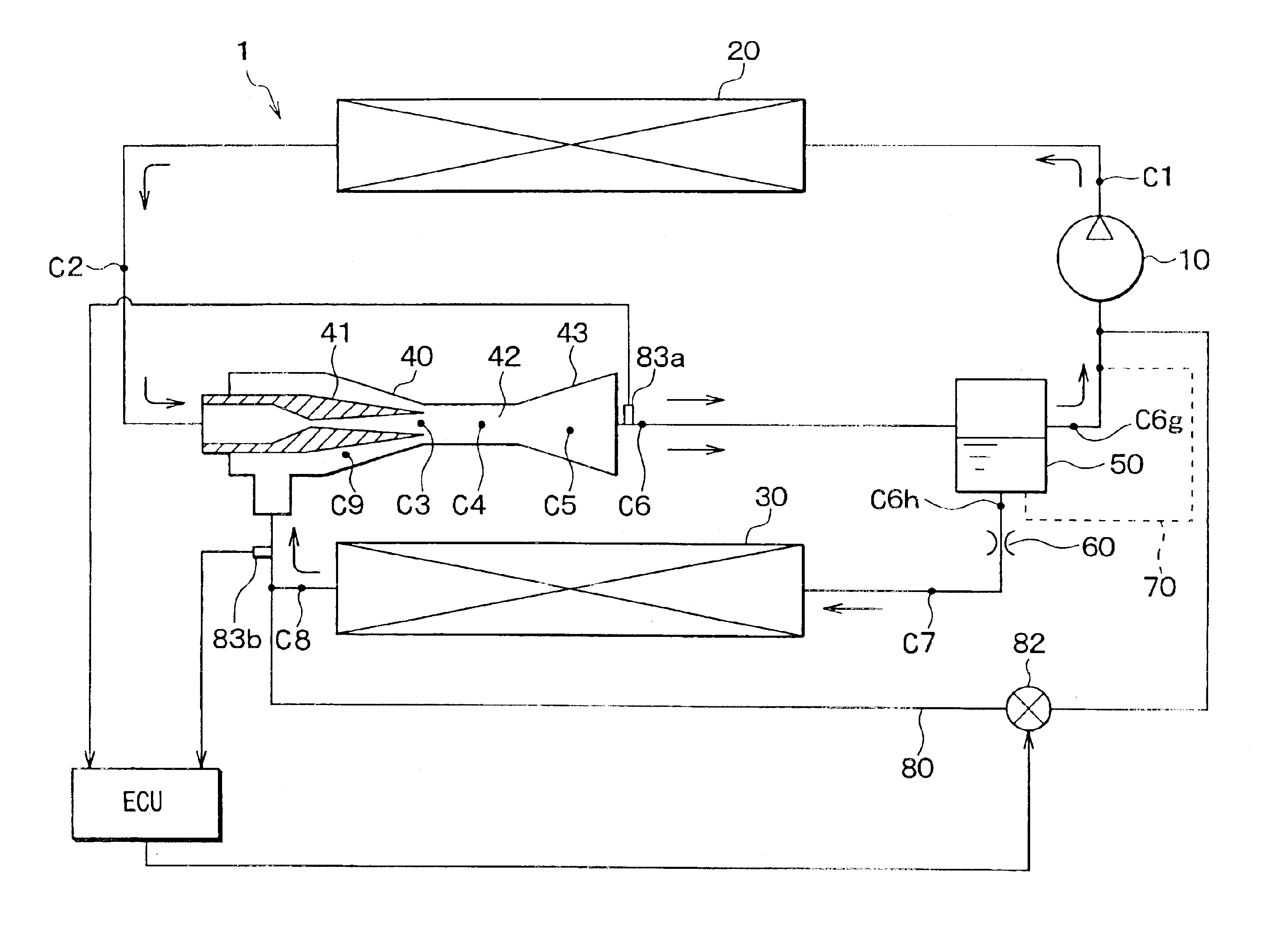
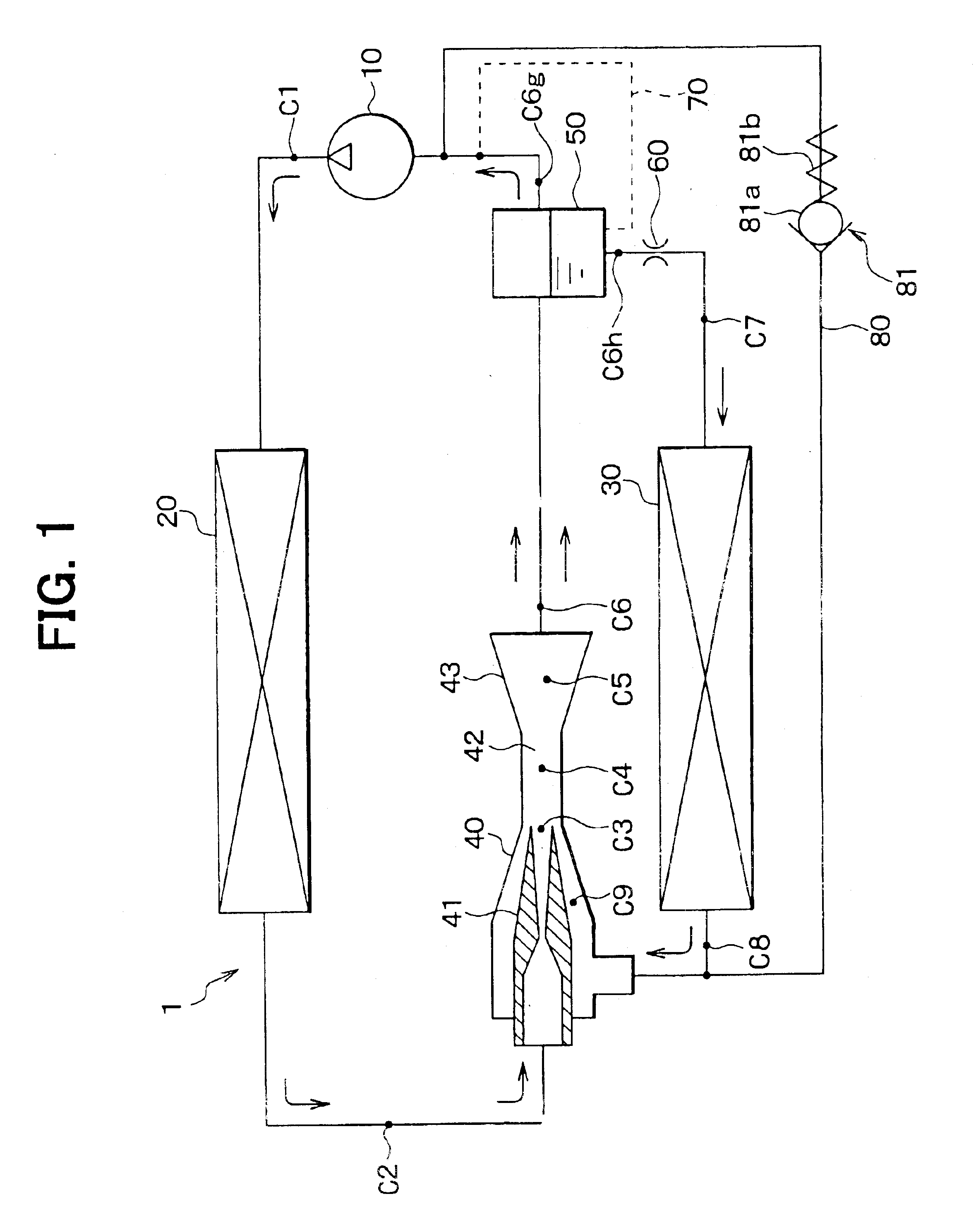
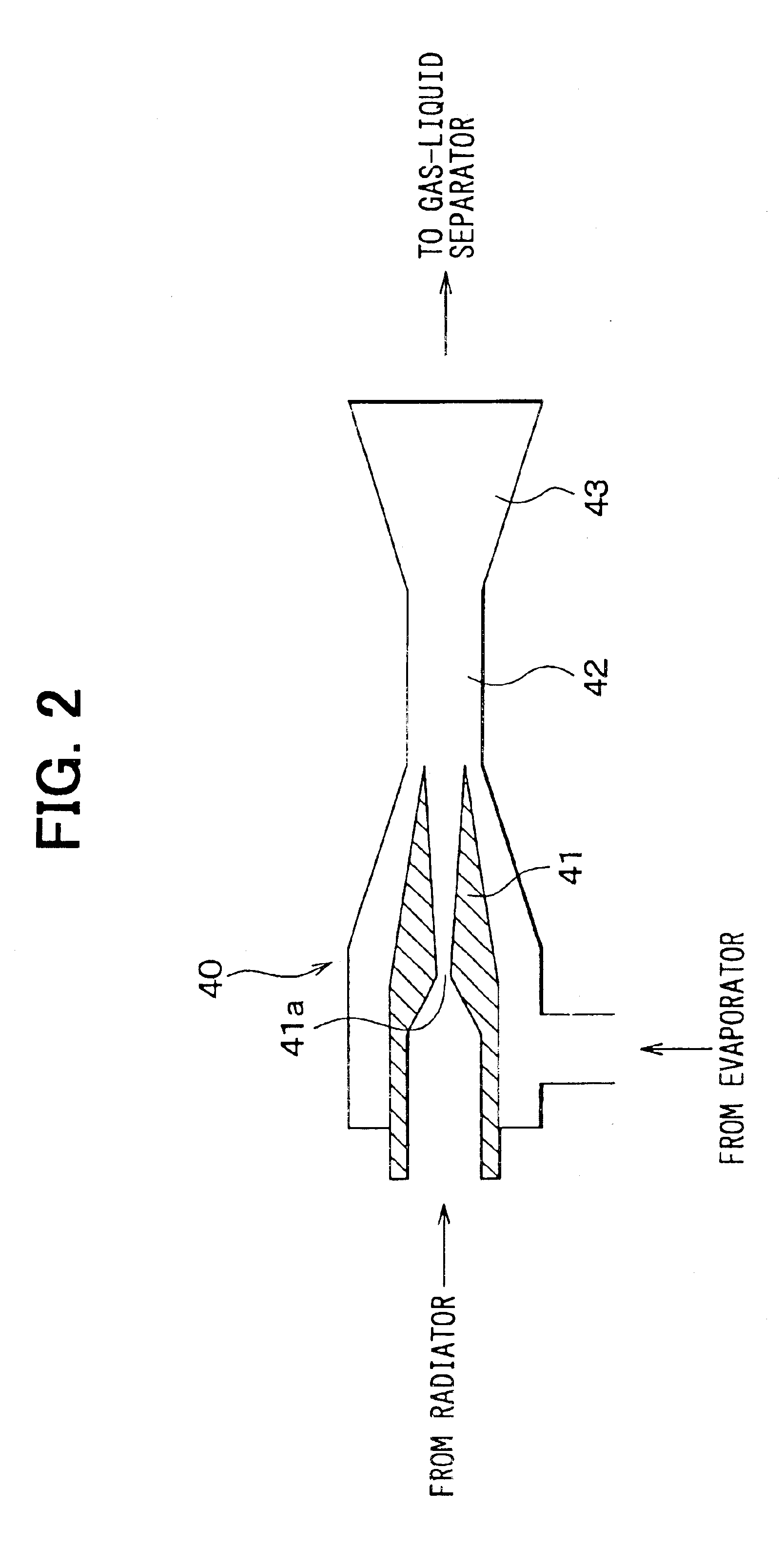
In the first embodiment, an ejector cycle according to the present invention is typically used for a vapor compression refrigerator used for a showcase for refrigerating foods. In FIG. 1, a compressor 10 is an electric compressor for sucking and compressing refrigerant circulated in an ejector cycle 1. A radiator 20 is a high-pressure heat exchanger for cooling high-temperature and high-pressure refrigerant discharged from the compressor 10 by performing heat-exchange operation between outside air and the high-temperature and high-pressure refrigerant. Further, an evaporator 30 is a low-pressure heat exchanger for cooling air to be blown into the showcase by evaporating liquid refrigerant, more specifically, by performing heat-exchange operation between the air and low-pressure refrigerant. An ejector 40 sucks refrigerant evaporated in the evaporator 30 while decompressing and expanding refrigerant flowing out from the radiator 20 in a nozzle 41, and increases pressure of refrigeran...

second embodiment

In the above-described first embodiment, the second oil return passage 80 is opened and closed by the check valve 81 constructed with a mechanical valve. In the second embodiment, as shown in FIG. 8, a solenoid valve 82 is provided in the second oil return passage 80 in place of the check valve 81. Further, the pressure increasing value .DELTA.P in the ejector 40 is detected by pressure sensors 83a, 83b. When the pressure increasing value .DELTA.P detected by the pressure sensors 83a, 83b is equal to or smaller than a predetermined value, the solenoid valve 82 is closed by an electronic control unit (ECU). On the other hand, when the pressure increasing value .DELTA.P detected by the pressure sensors 83a, 83b exceeds the predetermined value, the solenoid valve 82 is closed by the ECU. Here, a predetermined value when the solenoid valve 82 is closed can be set different from a predetermined value when the solenoid valve 82 is opened. In the second embodiment, the solenoid valve 82 is...

third embodiment

The third embodiment of the present invention will be now described with reference to FIGS. 9-12. In the third embodiment, as shown in FIGS. 9-12, a bypass passage 90, into which high-pressure refrigerant flows while bypassing at least the nozzle 41, is directly connected to the evaporator 30. In the third embodiment, the second oil return passage 80 described in the above first and second embodiments is not provided. A three-way valve 91 is provided at a branch point of the bypass passage 90 and a high-pressure refrigerant passage coupled to the nozzle 41 of the ejector 40. The three-way valve 91 is disposed to switch a refrigerant flow into the bypass passage 90. An expansion valve 93 is provided in the bypass passage 90, and decompresses and expands refrigerant in the bypass passage 90. When the pressure increasing value .DELTA.P in the ejector 40 is equal to or lower than a predetermined pressure, or when the ejector efficiency .eta.e is equal to or lower than a predetermined ef...


PUM


Abstract

In an ejector cycle having an ejector for decompressing refrigerant, a check valve is disposed in an oil return passage through which refrigerant including a lubrication oil is introduced from a refrigerant outlet side of an evaporator to a refrigerant suction side of a compressor while bypassing the ejector. When the lubrication oil amount staying in the evaporator reduces, the check valve is automatically closed, and a normal operation mode of the ejector cycle is automatically set. On the contrary, when a large amount of lubrication oil stays in the evaporator, the check valve is automatically opened, and an oil return mode is automatically set. Therefore, the lubrication oil staying in the evaporator can be controlled equal to or lower than a predetermined amount, thereby effectively returning the lubrication oil to the compressor.

Description

This application is related to and claims priority from Japanese Patent Applications No. 2002-198884 filed on Jul. 8, 2002 and No. 2002-200009 filed on Jul. 9, 2002, the contents of which are hereby incorporated by reference.1. Field of the InventionThe present invention relates to an ejector cycle with a refrigerant passage through which refrigerant including a lubrication oil is circulated directly by pumping operation of a compressor from an evaporator to a suction side of the compressor while bypassing at least a nozzle of an ejector.2. Description of Related ArtGenerally, as a vapor compression refrigerant cycle, an ejector cycle, an expansion-valve cycle or the like is used. In the expansion-valve cycle, refrigerant is decompressed by a decompression device such as an expansion valve in is enthalpic, and refrigerant decompressed in the decompression device flows into an evaporator. That is, in the expansion-valve cycle, refrigerant is circulated from a compressor to the compre...

Claims


Application Information

Patent Timeline
Patent Type & Authority Patents(United States)
IPC IPC(8): B60H1/32F25B41/00F25B9/00F25B31/00F25B40/00F25B5/02F25B5/00
CPCB60H1/3204F25B9/008F25B31/004F25B40/00F25B41/00B60H1/3214F25B2600/2501B60H2001/3297B60H2001/3298F25B5/02F25B2309/061F25B2341/0011F25B2341/0012F25B2341/0013F25B2400/0407F25B2500/18
Inventor TAKEUCHI, HIROTSUGUOSHITANI, HIROSHISAITO, MIKA
Owner DENSO CORP
Why Eureka
Try Eureka