Optical scanning device and image forming apparatus including the optical scanning device

a scanning device and optical scanning technology, applied in the field of optical scanning devices and image forming apparatus, can solve the problems of high device cost, difficult auto-assembly of scanning device optical system, and inability to easily accomplish assembly work

Inactive Publication Date: 2004-12-28
RICOH KK
View PDF24 Cites 17 Cited by
  • Summary
  • Abstract
  • Description
  • Claims
  • Application Information

AI Technical Summary

Benefits of technology

According to another aspect of the present invention, an optical scanning device includes a moving carriage carrying an exposure optical system, a timing belt positioned along a sub-scanning direction to reciprocate the moving carriage in the sub-scanning direction, and a belt clamp mechanism detachably clamping the timing belt to the moving carriage, the belt clamp mechanism including, a plurality of comb-tooth members provided to a lower surface of the moving carriage spaced apart in the sub-scanning direction by a gap such that the plurality of comb-tooth members protrude from the lower surface of the moving carriage toward the timing belt, and a clamp member having a support surface having a protrusion protruding toward the gap between the plurality of comb-tooth members. The clamp member is secured to the moving carriage such that the clamp member opposes the plurality of comb-tooth members via the timing belt while the protrusion on the support surface pressing the timing belt into the gap between the pair of comb-tooth members.

Problems solved by technology

(1) The wiring of driving wires is so complicated that assembly work may not be easily accomplished. Therefore, auto-assembly of an optical system of a scanning device may be difficult to perform.
(2) In order to prevent driving wires from being tangled, a predetermined tension is necessary to be applied to the driving wires. Because of complicated wiring of the driving wires, many pulleys are required to rotatably support the driving wires. For example, at least two pulleys are required at one side of the moving carriages. Due to the tension applied to the driving wires, the force in the radial direction is exerted on each of the pulleys. In this case, a ball bearing is often used for each of the pulleys to reduce a load on the pulley, driving the cost of the device higher.
In this case, the distance between a lens and an original document is minutely changed, causing deterioration of scanned images.
If the first and second moving carriages 104, 105 are attached to the timing belts, 116, 117, 118, and 119, at a plurality positions to avoid the above-described shifts of the attachment positions, assembly work inevitably may become complicated, thereby decreasing productivity.

Method used


Image

  • Optical scanning device and image forming apparatus including the optical scanning device
  • Optical scanning device and image forming apparatus including the optical scanning device
  • Optical scanning device and image forming apparatus including the optical scanning device

Examples


Embodiment Construction

Preferred embodiments of the present invention are described in detail referring to the drawings, wherein like reference numerals designate identical or corresponding parts throughout the several views.

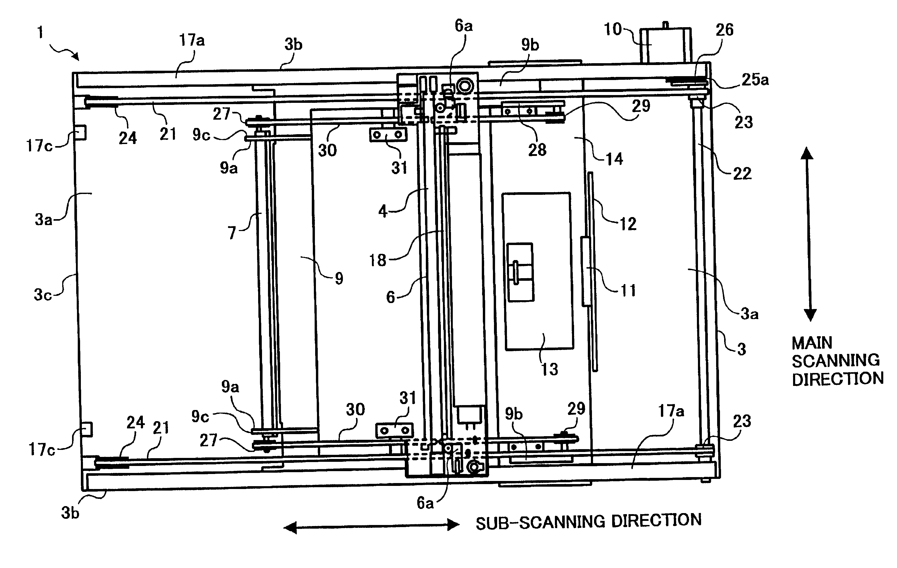
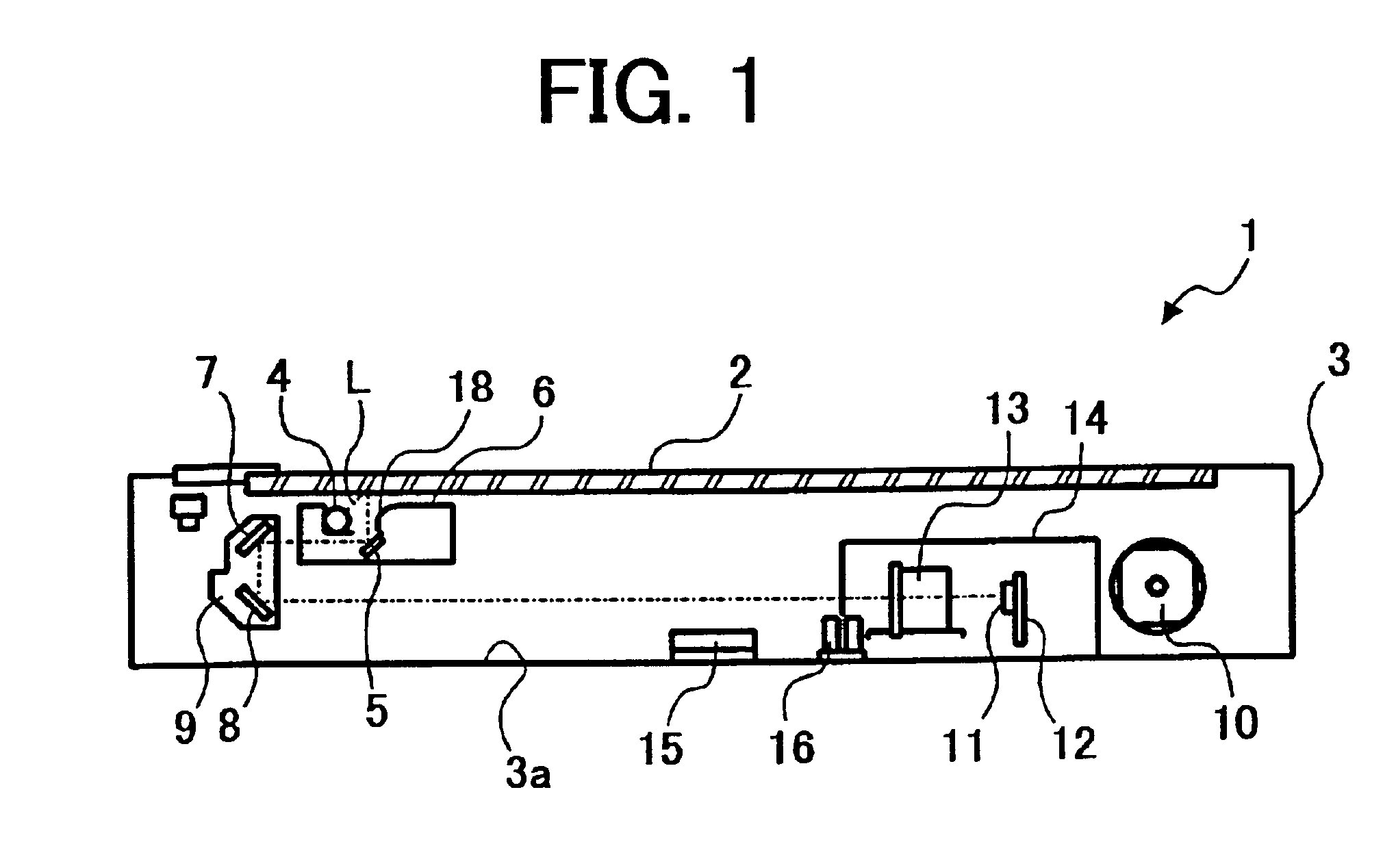
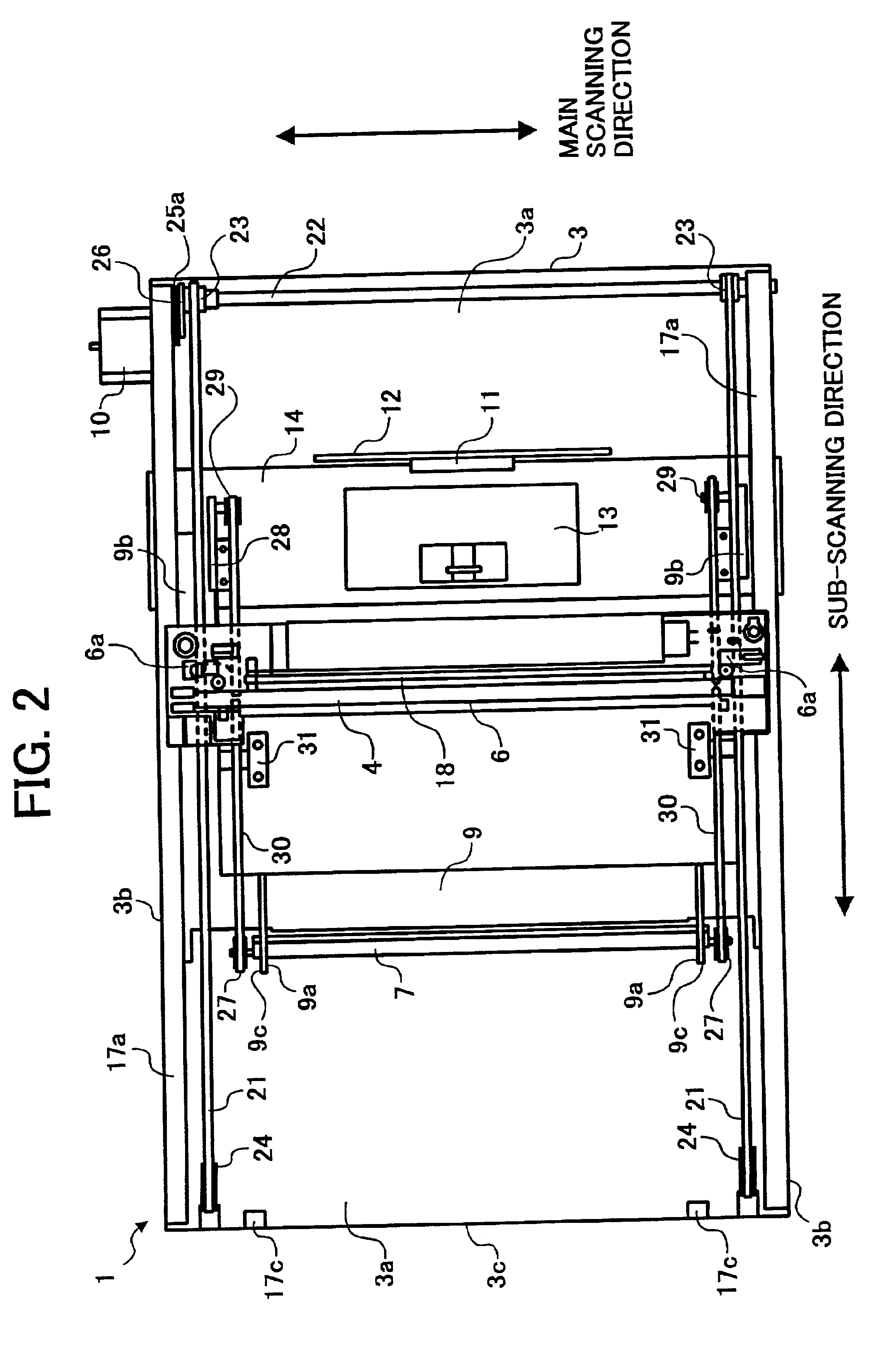
An optical scanning device according to an embodiment of the present invention is a flatbed scanner type that scans an original document immovably set on a contact glass. First, an overall construction of the optical scanning device will be described referring to FIG. 1. FIG. 1 is a schematic vertical longitudinal sectional side view of an optical scanning device 1 according to this embodiment of the present invention. The optical scanning device 1 includes a case-like housing 3 having a contact glass 2 at the upper surface of the housing 3 for setting original documents on the contact glass 2.

In the housing 3, there are provided a first moving carriage 6 and a second moving carriage 9. The first moving carriage 6 carries a xenon lamp 4 (hereinafter referred to as a "Xe lamp") serving...


PUM


Abstract

An optical scanning device including a housing, a first carriage carrying a light source and a first mirror, a second carriage carrying second and third mirrors, the second carriage cofigured to move in a sub-scanning direction at one-half of a speed of the first carriage, first and second timing pulleys spaced apart in the sub-scanning direction, a timing belt spanned around the first and second timing pulleys to reciprocate the first carriage in the sub-scanning direction, a drive device to drive the first timing pulley, flat pulleys supported by the second carriage and spaced apart in the sub-scanning direction by a moving distance of the second carriage, a flat belt spanned around the flat pulleys to reciprocate the second carriage in the sub-scanning direction, an engaging member engaging the timing and flat belts to the first carriage, and a fixing member fixing the flat belt to the housing.

Description

CROSS-REFERENCE TO RELATED APPLICATIONSThis document claims priority to Japanese Patent Application No. 2001-132597 filed in the Japanese Patent Office on Apr. 27, 2001, and Japanese Patent Application No. 2001-132594 filed in the Japanese Patent Office on Apr. 27, 2001. The entire contents of those applications are hereby incorporated herein by reference.BACKGROUND OF THE INVENTION1. Field of the InventionThe present invention relates to an optical scanning device and an image forming apparatus such as a copying machine, a facsimile machine, a printer, etc., including the optical scanning device.2. Discussion of the BackgroundGenerally, an optical scanning device of a flatbed scanner type that scans an image of an original document immovably set on a contact glass includes first and second moving carriages that move in a sub-scanning direction at a speed ratio of two to one. The first moving carriage carries a light source that irradiates an image surface of an original document wi...

Claims


Application Information

Patent Timeline
Patent Type & Authority Patents(United States)
IPC IPC(8): G03G15/04H04N1/10H04N1/191H04N1/193
CPCG03G15/04H04N1/1013H04N1/1056H04N1/1026G03G15/0435H04N1/193
Inventor BANNAI, KAZUNORIFUJIOKA, TETSUYA
Owner RICOH KK
Why Eureka
Try Eureka