
Weatherstrip for automobile

a technology for automobiles and weatherstrips, applied in the field of weatherstrips, can solve the problems of high cost, inability to easily carry out attachments, and increase the number of processes, and achieve the effect of preventing the weatherstrip from coming off the flange and preventing inclination

Inactive Publication Date: 2005-01-04
NISHIKAWA RUBBER
View PDF14 Cites 31 Cited by
  • Summary
  • Abstract
  • Description
  • Claims
  • Application Information

AI Technical Summary

Benefits of technology

The present invention provides a weatherstrip for automobiles that can reduce gaps without increasing components or processes. The weatherstrip has an attaching portion that is attached to the inner panel of the door by inserting a flange into an attaching means. The weatherstrip also has sealing portions that are elastically fitted to the window glass and a latching portion that is joined with the trim end by latching. This eliminates the need for a clip to join the trim end and reduces costs. The weatherstrip can be guided and latched with the trim end, preventing it from approaching the window glass too close. The invention also includes a concave groove and a glue for adhering the attaching portion to the flange, as well as a sloping or curved guide means for smooth and secure attachment of the trim. The weatherstrip has a rack portion and guide means for smoothly carrying out a shift of the trim end. The attaching portion has an inserting groove and a protrusion or thick-walled portion to prevent inclination. The weatherstrip can be latched with the flange using a claw portion and a hook-up portion on the flange.

Problems solved by technology

However, in the former method for filling up a gap with a component, the number of components increases and the number of processes increases, resulting in high cost.
Also, in the latter method, attachment cannot be easily carried out, the external appearance after attachment is not favorable, and damage to the weatherstrip and pillar garnish easily occurs.
According to this method, the trim end is laterally inserted to fit over the flange 26a and therefore need not climb over the flange, the gap c as shown in the foregoing FIG. 8 can be reduced, however, in this case as well, the number of components increases, resulting in high cost.

Method used


Image

  • Weatherstrip for automobile
  • Weatherstrip for automobile
  • Weatherstrip for automobile

Examples


Embodiment Construction

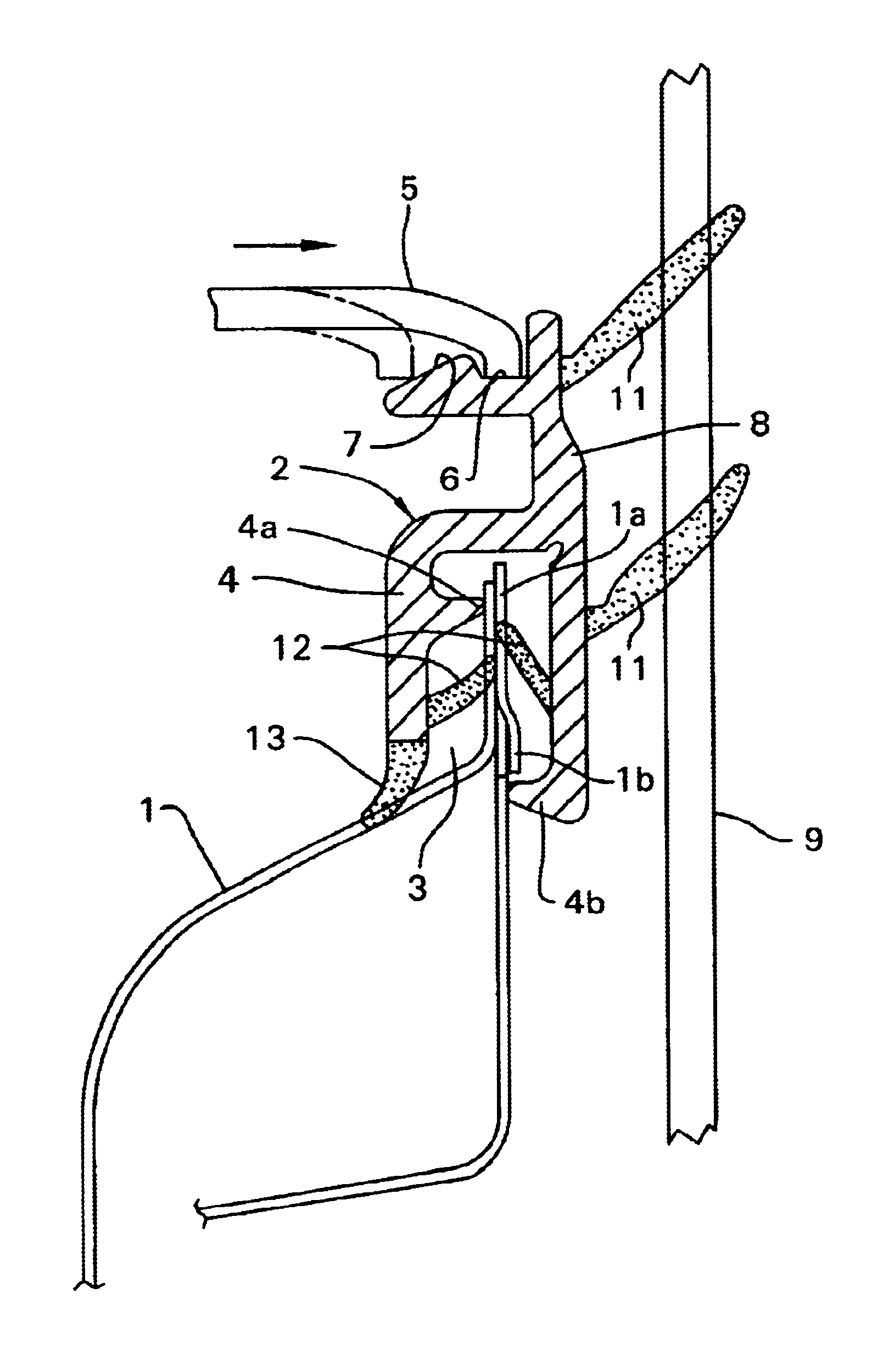
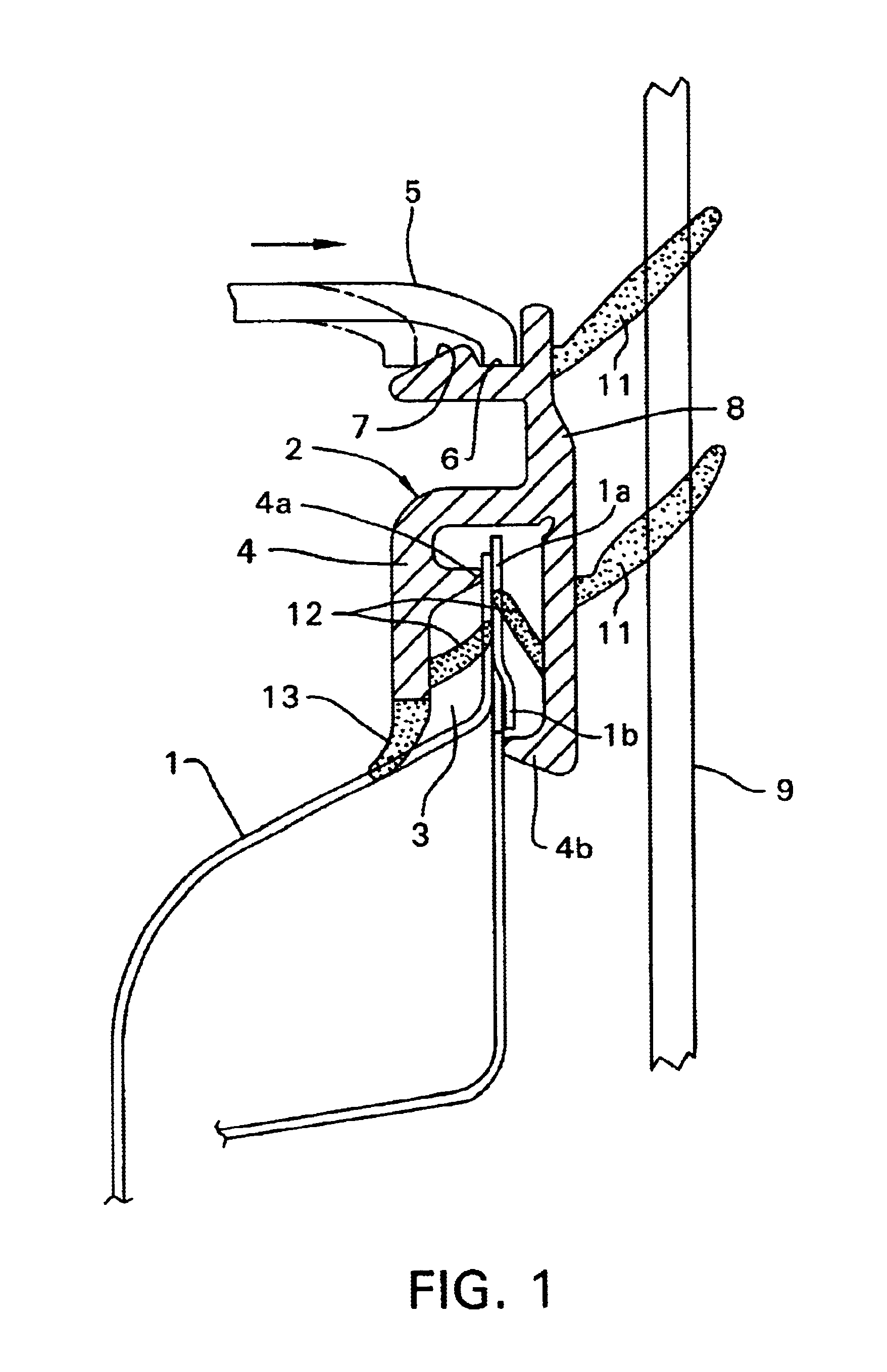
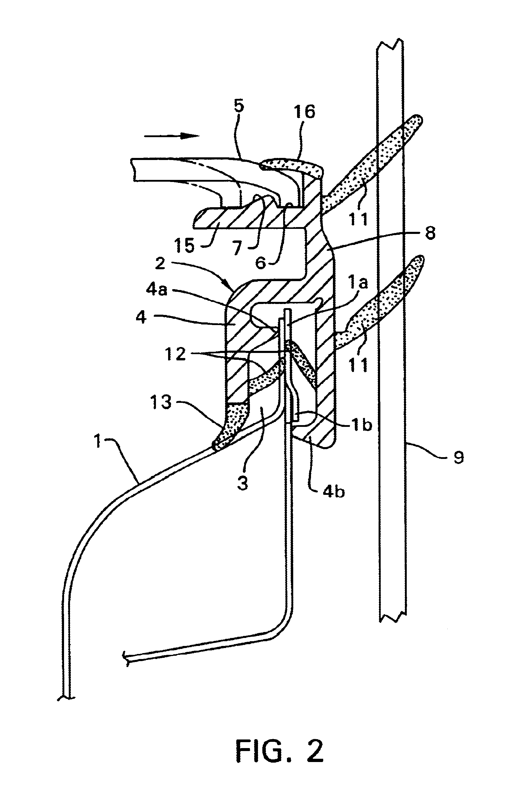
FIG. 1 shows a weatherstrip 2 attached to a flange 1a on the upper edge of an inner panel 1 of automobile beltlines BL shown in FIG. 7. This weatherstrip 2 comprises: an attaching portion 4 which has an inserting groove 3 to be inserted over a flange 1a and thus forms an inverse U-shape in terms of its section; a rising portion 8 formed in a protruding manner on this attaching portion 4; and lip pieces 11 which are provided in a laterally protruding manner from the above attaching portion 4 and rising portion 8 and serve as sealing portions for sealing between the door inner panel and a window glass 9 by being elastically fitted to the window glass 9; wherein

in said attaching portion 4, on one side of the inside thereof, a inclination-preventive protrusion 4a which is inwardly protruded and makes contact with a side surface of the flange 1a and thereby prevents the attaching portion 4 from inclining clockwise is formed in a protruding manner, and below the protrusion on the inside o...


PUM


Abstract

A weatherstrip for an automobile includes an attaching portion having an inverse U-shape cross section. A rising portion is formed in a protruding manner on the attaching portion and lip pieces are formed for sealing between a door inner panel and a window glass. The rising portion includes a sloping guide that leads to a concave groove with which the trim end of a trim is fitted and latched. To attach the weatherstrip to the upper edge of an inner panel of a door beltline, the attaching portion is attached to the flange by insertion. Then the trim end of the trim is pressed against the guide and is, thrust so as to be fitted and latched with the concave groove. Since the trim end need not climb over the flange while keeping a weatherstrip attached thereto, even if the angle created by the door beltline and a pillar is an acute angle, the creation of a large gap between the weatherstrip end and the pillar is eliminated.

Description

BACKGROUND OF THE INVENTIONThe present invention relates to a weatherstrip to be attached to a car door panel for sealing between the same and a window glass and, in particular, to a weatherstrip to be attached to the upper edge of a door inner panel of a door beltline.As this type of weatherstrip, there is a weatherstrip 21 which is, as shown in FIG. 6, attached to the trim 23 end portion as a door interior material joined to an inner panel 22. In an automobile door having the structure shown in FIG. 6, joining of the trim 23 to the inner panel 22 is carried out in such a manner that the trim 23 is slightly lifted and thrust into the inner panel 22, is then dragged down to latch the trim end with a flange 22a of the inner panel 22, and for joining the trim 23 to the inner panel 22, the trim end needs to climb over the flange.However, as with an automobile shown in FIG. 7, in a case where the angles of corner portions A and B created by a beltline BL, a front pillar 24, and a rear p...

Claims


Application Information

Patent Timeline
Patent Type & Authority Patents(United States)
IPC IPC(8): B60J10/00B60J10/02B60J10/04
CPCB60J10/0005B60J10/041B60J10/0068B60J10/0051B60J10/16B60J10/265B60J10/33B60J10/75
Inventor ARATA, MITHUAKIHAMANAKA, HITOSHIYOSHIOKA, KENTOKUTOMI, KAZUHIKO
Owner NISHIKAWA RUBBER
Learn More