
Buffer packing apparatus

a buffer packing and apparatus technology, applied in the field of buffer packing apparatus, can solve the problem of the entire buffer packing apparatus's buffering capacity being collapsed,

Inactive Publication Date: 2005-01-04
ARIMA COMP
View PDF8 Cites 10 Cited by
  • Summary
  • Abstract
  • Description
  • Claims
  • Application Information

AI Technical Summary

Benefits of technology

Accordingly, one object of the present invention is to provide a buffer packing apparatus that provides a space for accommodating an object and protecting the object from possible damage due to an external impact.
In yet another embodiment of this invention, buffer columns comprising just a U-shaped column body are set on some of the corners of the rectangular partition boards. Buffer columns comprising a pair of U-shaped column bodies connected via a connecting wall are set on the remaining corners of the rectangular partition boards. With this arrangement, packaging personnel can easily identify the orientation of various objects inside the packing apparatus.
In addition, the chamfers on the rectangular partition boards provide an additional gap between the outer edges each buffer column and a packing box after the buffer packing apparatus is lowered into a packing box. Hence, the degree of damage to the buffer columns when the packing box receives an external impact will be greatly minimized. In other words, the buffer packing apparatus of this invention will have a higher structural strength.

Problems solved by technology

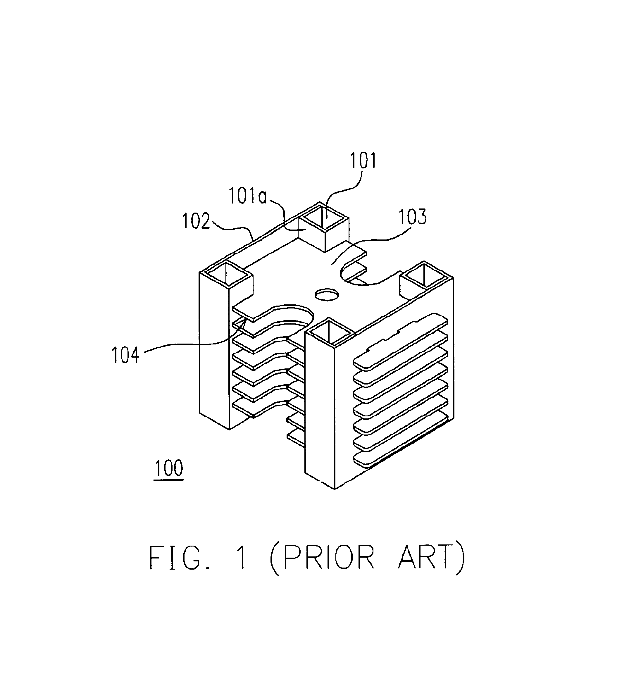
Hence, any external impact on the packing box is likely to cause some structural damage to the buffer column 101 leading to possible collapse of the buffering capacity of the entire buffer packing apparatus.

Method used


Image

  • Buffer packing apparatus
  • Buffer packing apparatus
  • Buffer packing apparatus

Examples


Embodiment Construction

Reference will now be made in detail to the present preferred embodiments of the invention, examples of which are illustrated in the accompanying drawings. Wherever possible, the same reference numbers are used in the drawings and the description to refer to the same or like parts.

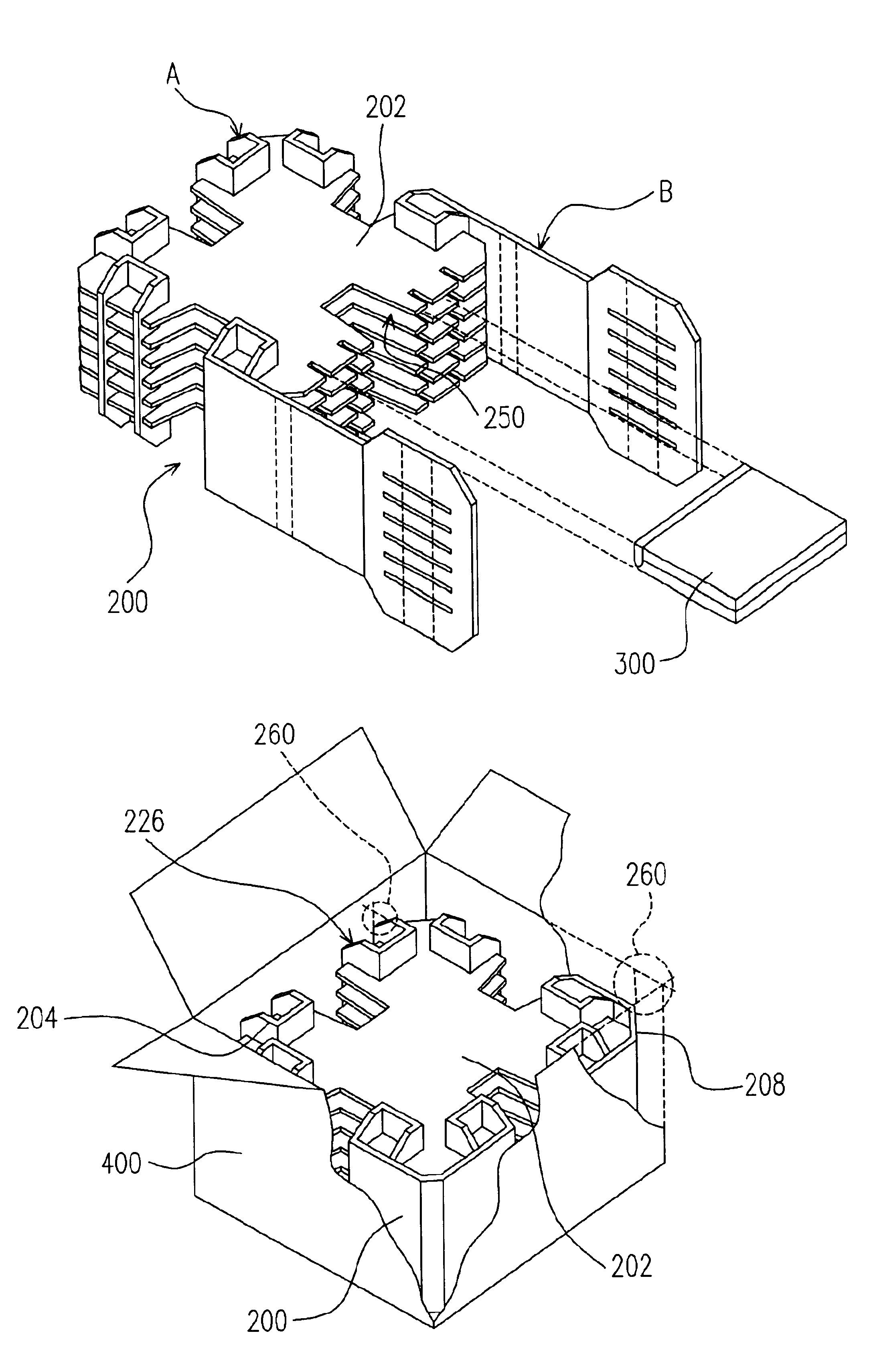
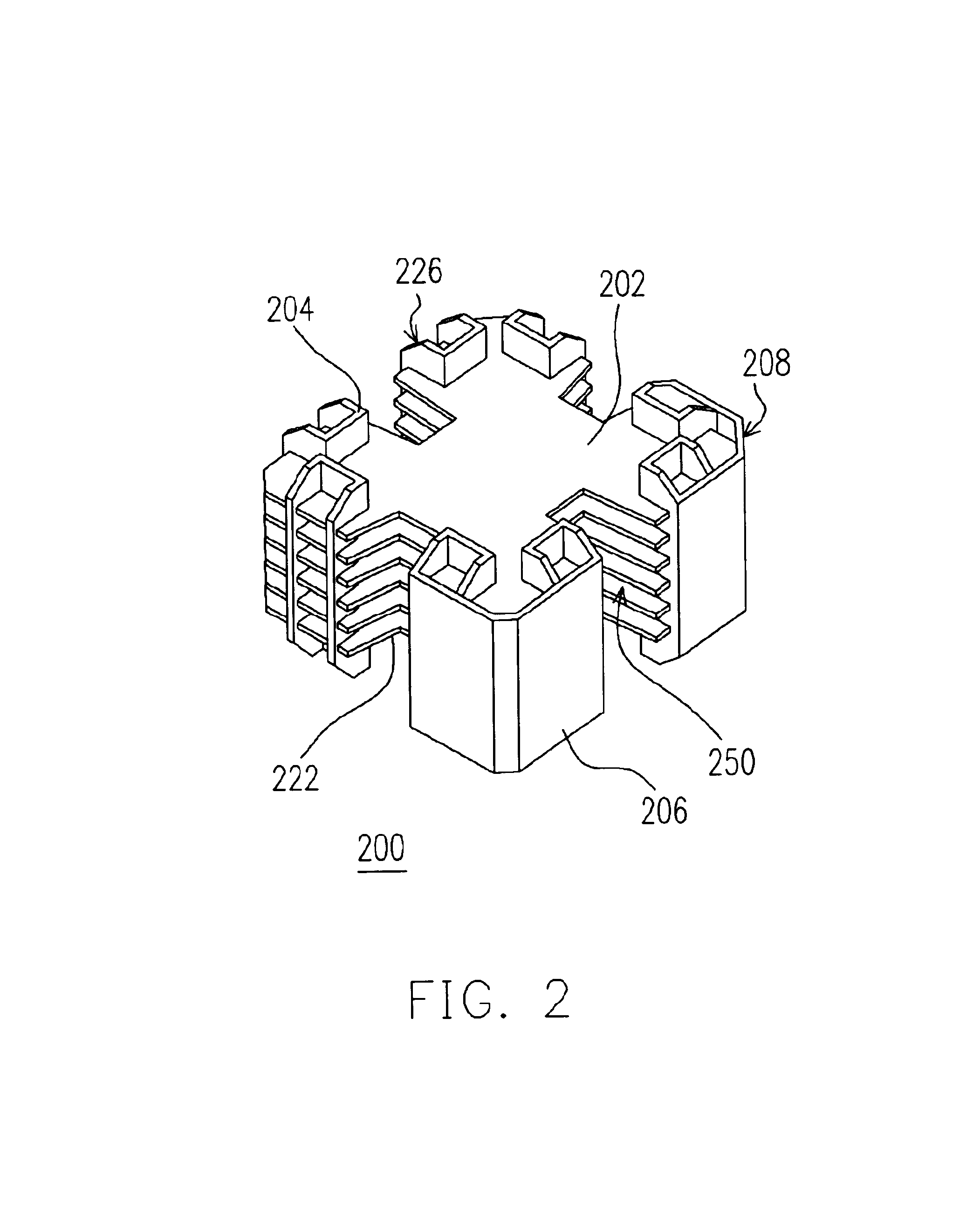
FIG. 2 is a perspective view showing a buffer packing apparatus according one embodiment of this invention. FIG. 3 is an exploded view showing the components of a buffer packing apparatus according to one embodiment of this invention. As shown in FIG. 3, the buffer packing apparatus 200 comprises a plurality of rectangular partition boards 202, eight U-shaped column bodies 204 and a pair of connecting walls 206. The rectangular partition boards 202 are set at a fixed distance apart but parallel to each other. All corners of each rectangular partition board are chamfered 208. Furthermore, the two side edges of the rectangular partition board close to each chamfer 208 has a set (for example, two) of first sl...


PUM


Abstract

A buffer packing apparatus for packing a plurality of objects is provided. The buffer packing apparatus comprises a plurality of rectangular partition boards and a plurality of buffer columns. The rectangular partition boards form a plurality of compartments for buffering and accommodating the objects. Through the selection of different buffer column designs, orientation of the objects inside the buffer packing apparatus can be easily identified. With chamfers on every corner of the buffer packing apparatus, the shock produced by an external impact can be readily absorbed thereby increasing the buffering capacity of the packing.

Description

BACKGROUND OF INVENTION1. Field of the InventionThe present invention relates to a buffer packing apparatus. More particularly, the present invention relates to a buffer packing apparatus for packing a plurality of objects.2. Description of the Related ArtBefore packing up an object for transportation, some buffering material is normally placed inside a packaging box to pack the object and provide some space for buffering damages due to impact. In the earlier days, lightweight and easy-to-manufacture buffering materials such as polyurethane or plastic were used. In recent years, however, with environmental protection fresh in everybody's mind, material fabricated from paper gradually replaces the conventional polyurethane or plastic in packing things up for delivery. Nowadays, the most common buffering material includes molded packing apparatus or properly cut and folded cardboard. Because folded cardboard is easier and cheaper to manufacture, this type of packing is wildly used.FIG...

Claims


Application Information

Patent Timeline
IPC IPC(8): B65D81/05B65D5/49B65D5/48
CPCB65D81/05B65D5/48024
Inventor LI, MING-WEIYU, CHIA-CHEN
Owner ARIMA COMP
Learn More