Indirect luminaire optical system

a technology of indirect luminaires and optical systems, applied in the field of indirect office environment fluorescent tube lighting fixtures, can solve the problems of affecting worker comfort and productivity, less efficient fixtures, and false ceiling impressions, and achieve the effect of high efficiency

Inactive Publication Date: 2005-01-04
GENLYTE THOMAS GRP LLC
View PDF13 Cites 23 Cited by
  • Summary
  • Abstract
  • Description
  • Claims
  • Application Information

AI Technical Summary

Benefits of technology

It is an object of the present invention to provide an indirect fluorescent tube overhead lighting

Problems solved by technology

Such glare and reflection is an undesirable effect which impacts worker comfort and productivity.
A problem, however, with mounting the fixtures a significant distance below the ceiling is that a ‘false ceiling’ impression is created by the rows of fixtures needed to illuminate a large work area.
Previous efforts to design fixtu

Method used


Image

  • Indirect luminaire optical system
  • Indirect luminaire optical system
  • Indirect luminaire optical system

Examples


Embodiment Construction

1. Suspended Single Lamp Luminaire Optical System

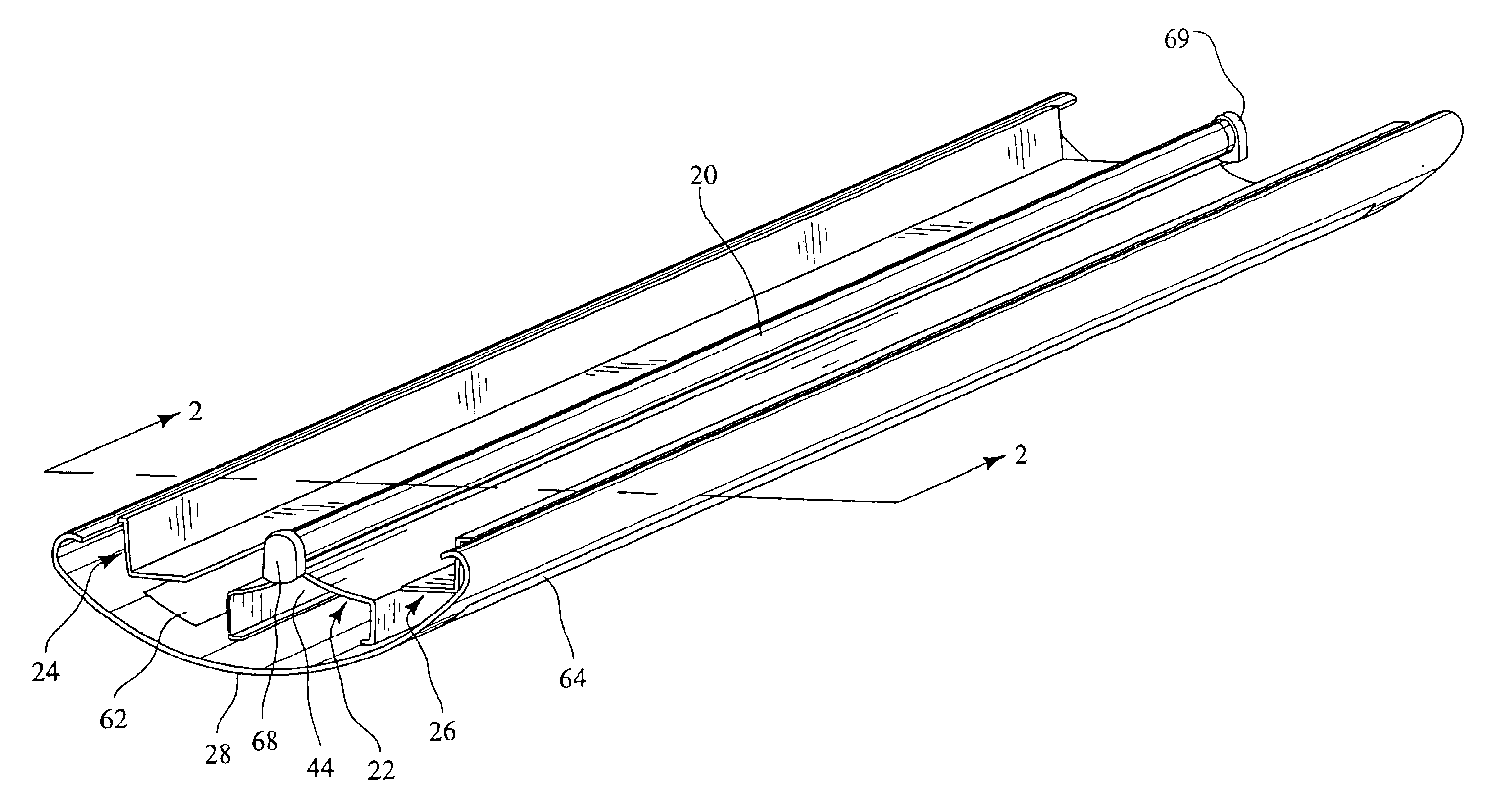
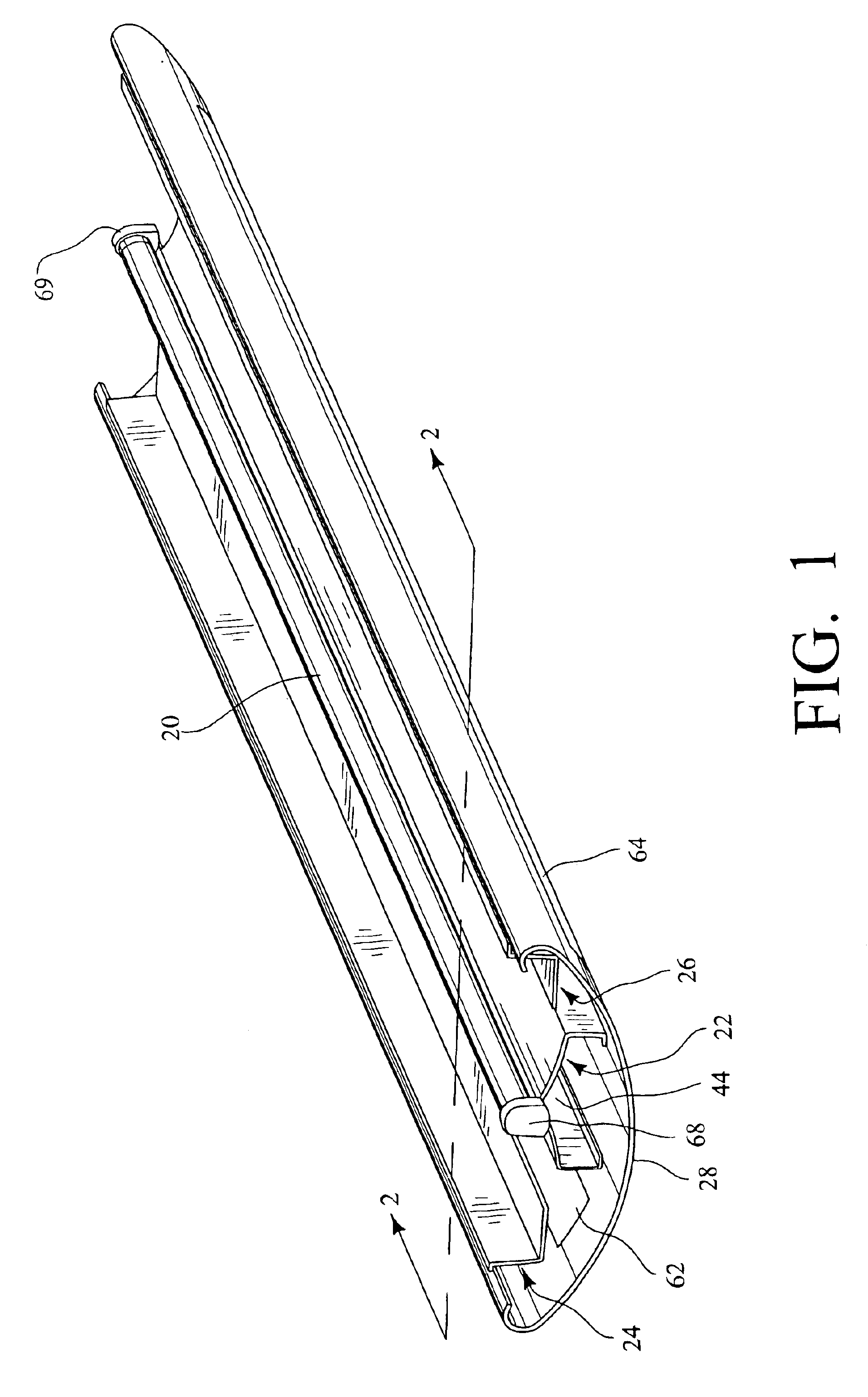
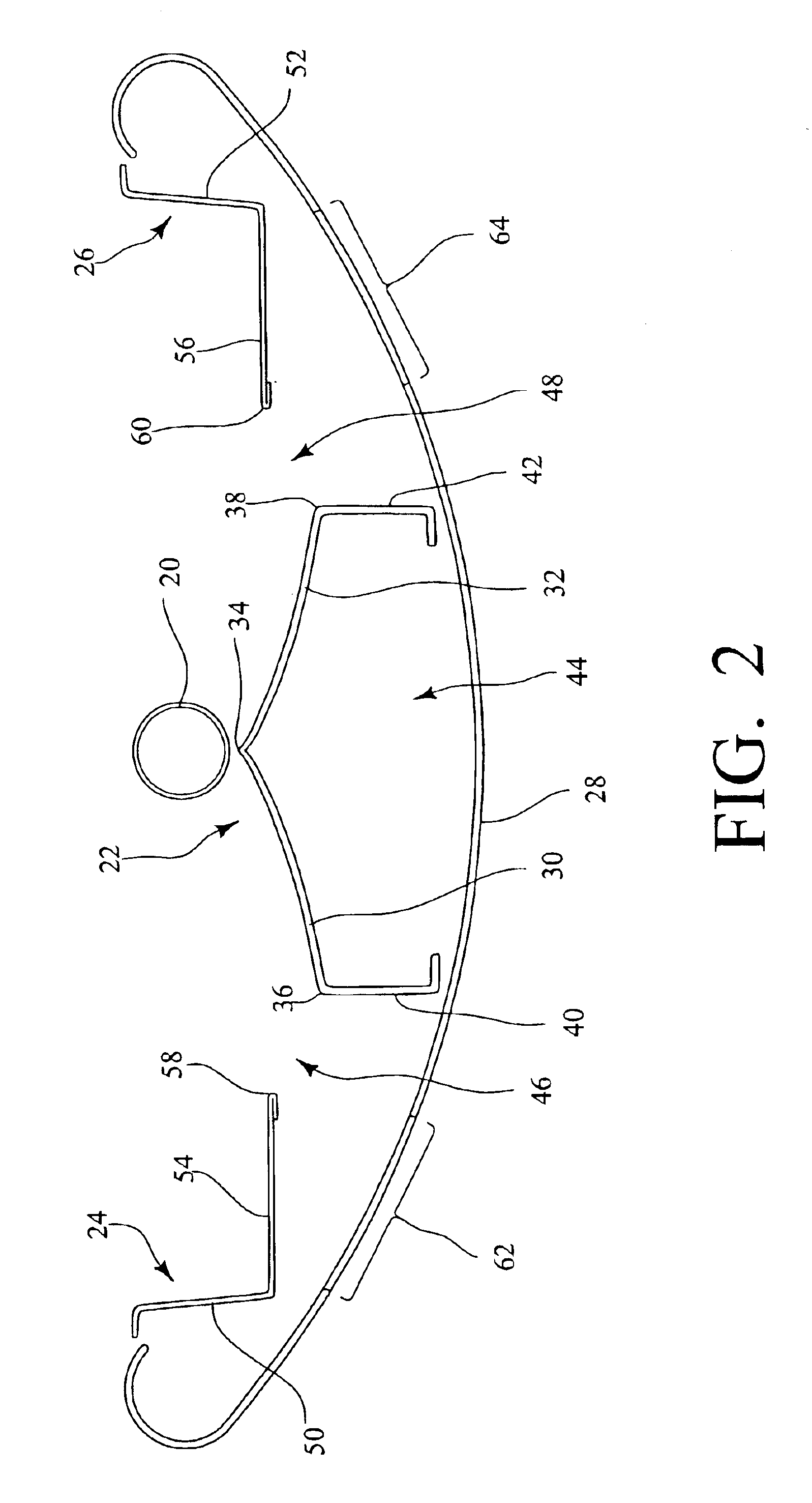
As shown in FIGS. 1 and 2, the luminaire optical system of one embodiment of the invention comprises a single tubular lamp 20, a parabolic reflector assembly 22, a pair of kick reflector assemblies 24, 26 and a housing 28.

The tubular lamp 20 of the single lamp embodiment may be a 54-watt T5 high output type fluorescent lamp, but one skilled in the art will recognize that the benefits of the optical system of the invention will be realized with any tubular lamp.

As shown in FIG. 2, the parabolic reflector assembly 22 has a pair of substantially parabolic shaped reflectors 30, 32 located beneath the lamp 20. The parabolic shaped reflectors 30, 32 are joined to form an apex 34 along and directly under the lamp 20, with the apex 34 lying in a vertical plane which passes through the longitudinal axis of the lamp 20. The parabolic shaped reflectors 30, 32 are symmetric with each other about the lamp axis vertical plane. Thus, a proximate edg...


PUM


Abstract

An indirect luminaire optical system having linear tubular lamps, parabolic reflector assemblies positioned under the lamps, kick reflectors positioned adjacent to the sides of the lamps, and a housing positioned around the lamps and reflectors, with the housing having a substantially open top for allowing light to exit the optical system. Each parabolic reflector assembly may have a pair of substantially parabolic shaped reflectors joined to form a apex along and directly under the corresponding lamp lamp. The kick reflectors may be in a spaced relationship with the parabolic reflector assemblies, thereby defining openings therebetween. The bottom portion of the housing may have translucent areas which are in optical communication with the lamp through the openings.

Description

STATEMENT REGARDING FEDERALLY SPONSORED RESEARCH OR DEVELOPMENTNot applicable.REFERENCE TO A “SEQUENTIAL LISTING,” A TABLE, OR A COMPUTER PROGRAM LISTING APPENDIX SUBMITTED ON A COMPACT DISCNot applicable.BACKGROUND OF THE INVENTION1. Field of the InventionThe present invention relates to lighting fixtures for indirect room illumination through reflection of most of the fixture's light off of the room's ceiling, but also having a small, aesthetically pleasing downward component. More particularly, this invention relates to indirect office environment fluorescent tube lighting fixtures which are mountable close to the ceiling while providing uniform illumination of the ceiling and a high efficiency fixture.2. Description of Prior ArtWith the recent proliferation of Video Display Terminals (VDTs) in the office environment, lighting designers have identified high contrast overhead lighting as a source of glare and reflection on VDT screens. Such glare and reflection is an undesirable e...

Claims


Application Information

Patent Timeline
IPC IPC(8): F21V7/00F21V11/00F21V11/14
CPCF21V7/0016F21V7/0025F21V7/005F21W2131/402F21V11/14
Inventor DAHLEN, KEVIN S.
Owner GENLYTE THOMAS GRP LLC
Why Eureka
Try Eureka