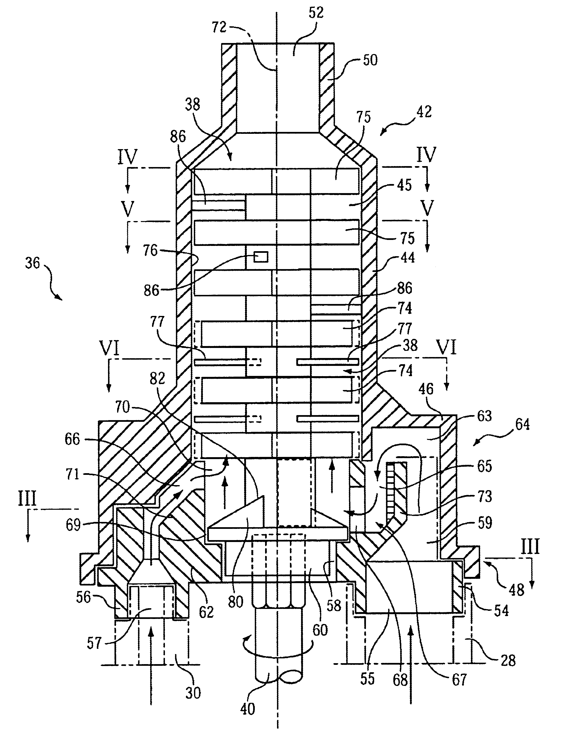
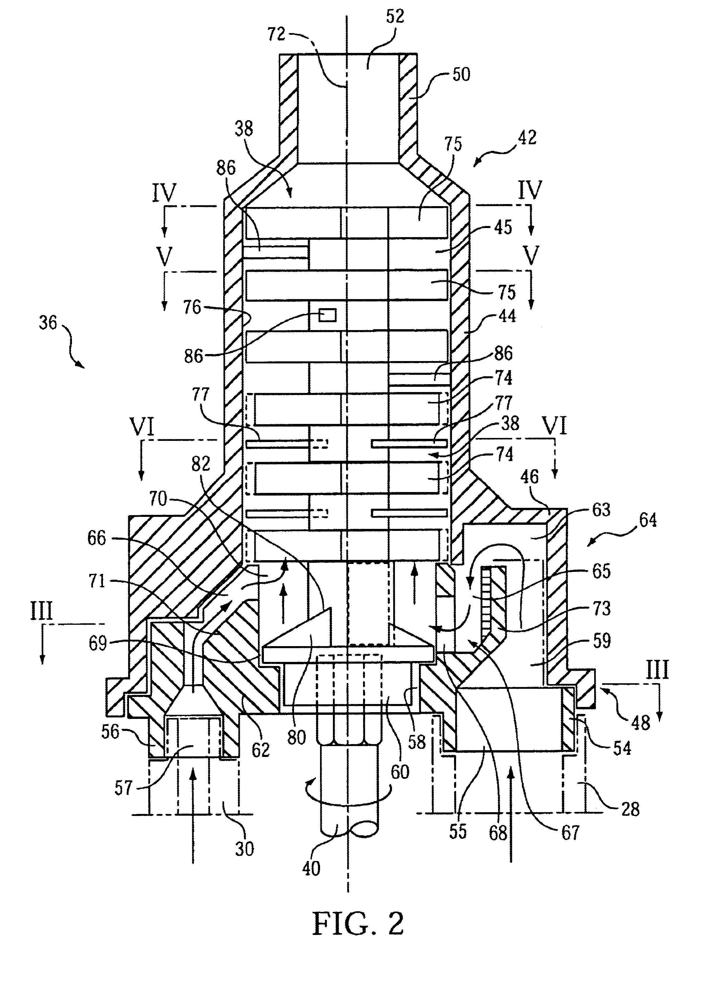
To compensate for the overdosage of one flow of compounds, the (first) duct assigned to this compound is designed to have a longer flow than the other (second) duct. This lengthening is achieved by extending the pertinent duct initially from the inlet opening of the coupling section of the mixer housing in the axial direction of the mixer element, or is formed as an arch around the axis of the mixer element. This duct is then a redirected preferably 180° and extends subsequently in the axial direction of the mixer element, or in the form of an arch around the axis of the mixer element, so that it ends, after being redirected 90° to 180° in the inlet opening of the mixer area. This form of the duct saves space while still providing a tolerable flow resistance. At the same time, as a result of these designs of the duct, the inlet opening of the mixer area is situated close to the coupling opening. When the coupling openings are arranged at 180° to each other, the inlet openings lie far from each other so that this recontamination is prevented. Moreover, the increased flow resistance in the other or second duct can be compensated for by this duct design where the duct includes a lengthening section to avoid any recontamination.
The arrangement of the segments of the first duct are formed so that the longitudinal axes of the segments together with the longitudinal axis of the mixer element span a joint radial level, and has the
advantage of providing a space-saving form of the longer first duct. The segments of the first duct are preferably formed linearly. Alternatively, it is also possible that the ducts can be formed curvilinear or curved. However, in this case the curved longitudinal axis are arranged in turn in a joint radial level together with the (linear) longitudinal axis of the mixer element.
If the segments of the first duct extend in the form of an arch around the longitudinal axis of the mixer element, for example, they are formed over each other in an axial direction, wherein the redirection section is formed C-shaped, or it extends over 180°. In so doing, the compound flows at first in the first segment in the shape of an arch away from the coupling opening, and after redirecting, led back toward the inlet opening, which preferably lies near to the coupling opening. This design of the first duct is particularly space saving.
The form of the mixer is such that several ducts extend from one or both coupling openings. The ducts end in several inlet openings, which
discharge particularly uniformly in the section of the mixer housing with the mixer element. In addition to the improved fluidic performance of the paste-like compounds, it has the
advantage that the materials admitted into the mixing area can be better and more homogeneously mixed. The spatially distributed
insertion of each of the two compounds or at least of one of the two compounds, contributes to this because this distributed
insertion of both compounds or at least of one of the two compounds in the mixer area has the
advantage that a sort of premixing takes place through the portioning of the compounds flow into several inlet openings.
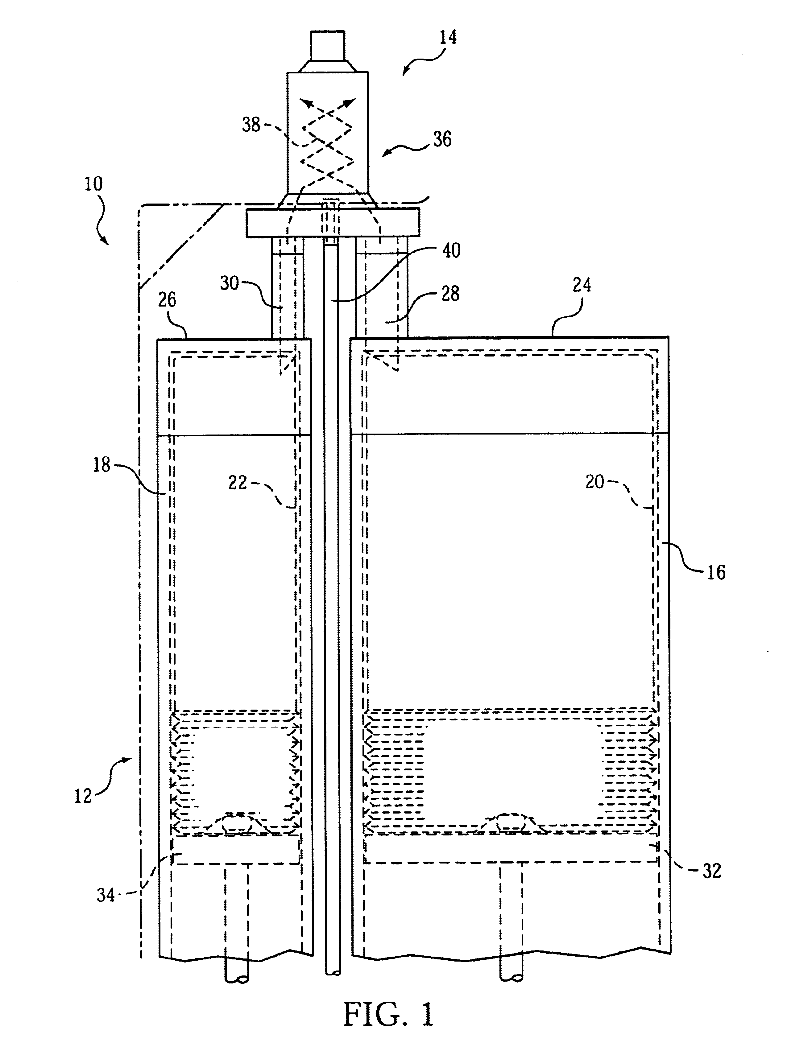
The invention has the benefit that several mixer arms are in the tube-shaped housing section between the radial inlet openings and the axial outlet opening. These arms protrude like a type of radial ribbing from the axis, and reach close to the inner surface of the tube-shaped housing section. These mixer arms are arranged within several radial levels from the shaft, and lead to a redirecting of the compounds flows that extend axially through the housing. Thus the desired mixing occurs through this. The
mixing effect is further strengthened if these mixing arms, which due to their radial alignment, prevent the direct flow between the inlet openings and the outlet opening, and extend to a larger
angular range, for example 90°. This can be achieved if adjacent mixer arms are connected to each other by a circumferential segment. In this way, therefore, mixer arms result that are formed like a type of quarter circles, whereby it can also be favorable if these quarter circles in their middle sections, as viewed in the circumferential direction, are more distant from the inner surface of the tube-shaped section of the housing in relation to their ends. It is practical if, from a first radial level to a second radial level, offset in the circumferential direction, two adjacent radial running mixer arms are respectively connected to each other in the way described above.
In a further advantageous embodiment of the invention, the mixer arms of the adjacent first radial levels, which are in the axial direction to the inlet openings of the tube-shaped section of the housing, are shorter than the mixer arms in the remaining second radial levels. Thus, the distance between the radial outlying ends of the mixer arms to the tube-shaped housing section within the first radial levels is greater than within the second radial levels. This leads to a larger mixer area in the area of the tube-shaped housing section, which connects to the inlet openings. This larger mixing area has the advantage that dosage tolerances conditioned by the squeezing or delivery device are better compensated. The material component moving ahead has a longer
retention period in the mixing area through the additional arrangement of the tangentially distant wiper elements within this enlarged mixing area. Through this, more time is available for mixing the slower material component with the material component moving ahead.

