Compensating element for a fuel injector valve

Inactive Publication Date: 2005-05-31
ROBERT BOSCH GMBH
View PDF12 Cites 29 Cited by
  • Summary
  • Abstract
  • Description
  • Claims
  • Application Information

AI Technical Summary

Benefits of technology

[0009]In contrast, an example embodiment of the compensating element according to the present invention may allow the fuel injector to be tilted with respect to the axis of the receiving bore, over a relatively large angular range, and may also allow a radial movement of the fuel injector from the center axis of the receiving bore. In

Problems solved by technology

It is disadvantageous, however, that the supporting body requires expensive manufacturing and that a precisely manufactured, spherical surface is needed.
Moreover, tolerance can only be compensated with respect to the specified geometry of the spherical surface.
A radial compensation movement purely with respect to the receiving bore is not possible.
A system described in German Published Patent Application No. 197 35 665, for forming the spherical surface on the cylinder head itself and thus, obviating a separate component part, has the additional disadvantage that the spherical surface requiring a high degree of accuracy must be formed in a bore, at the relatively large workpie

Method used


Image

  • Compensating element for a fuel injector valve
  • Compensating element for a fuel injector valve

Examples


Embodiment Construction

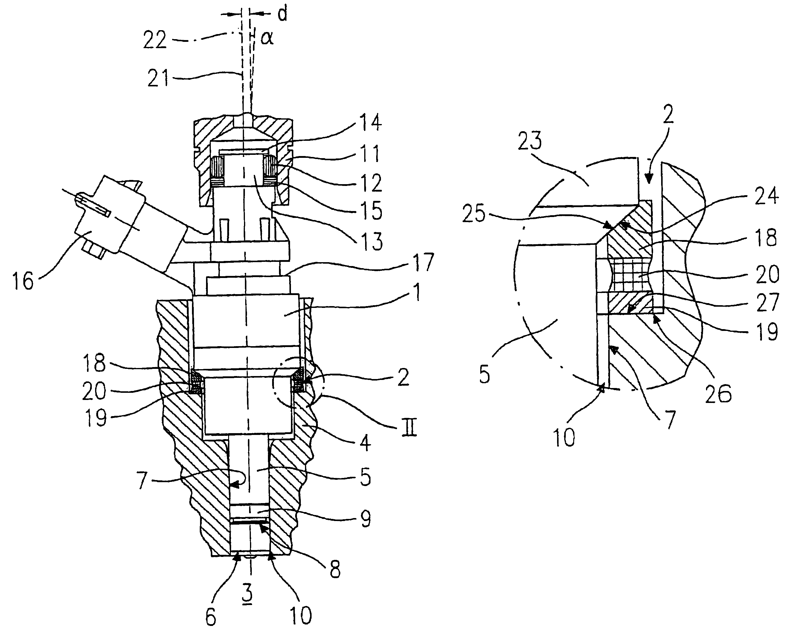
[0017]FIG. 1 illustrates a fuel injector 1 having a compensating element 2 according to the present invention. Fuel injector 1 is used for injecting fuel in the case of a mixture-compressing internal combustion engine having externally supplied ignition. Fuel injector is a high-pressure fuel injector for the direct injection of fuel into a combustion chamber 3 of the internal combustion engine, which is located beneath a cylinder head 4. However, compensating element 2 of the present invention may also be used in other cases.

[0018]Fuel injector 1 includes a nozzle body 5 having an ejection-side end 6, and is mounted in a receiving bore 7 of a cylinder head 4, a cross-sectional view of which is indirectly illustrated.

[0019]Furthermore, FIG. 1 illustrates a sealing ring 9 positioned in a groove 8 of nozzle body 5 on the side of the combustion chamber, which seals a ring gap 10 between nozzle body 5 and receiving bore 7, and is made of Teflon®, for example.

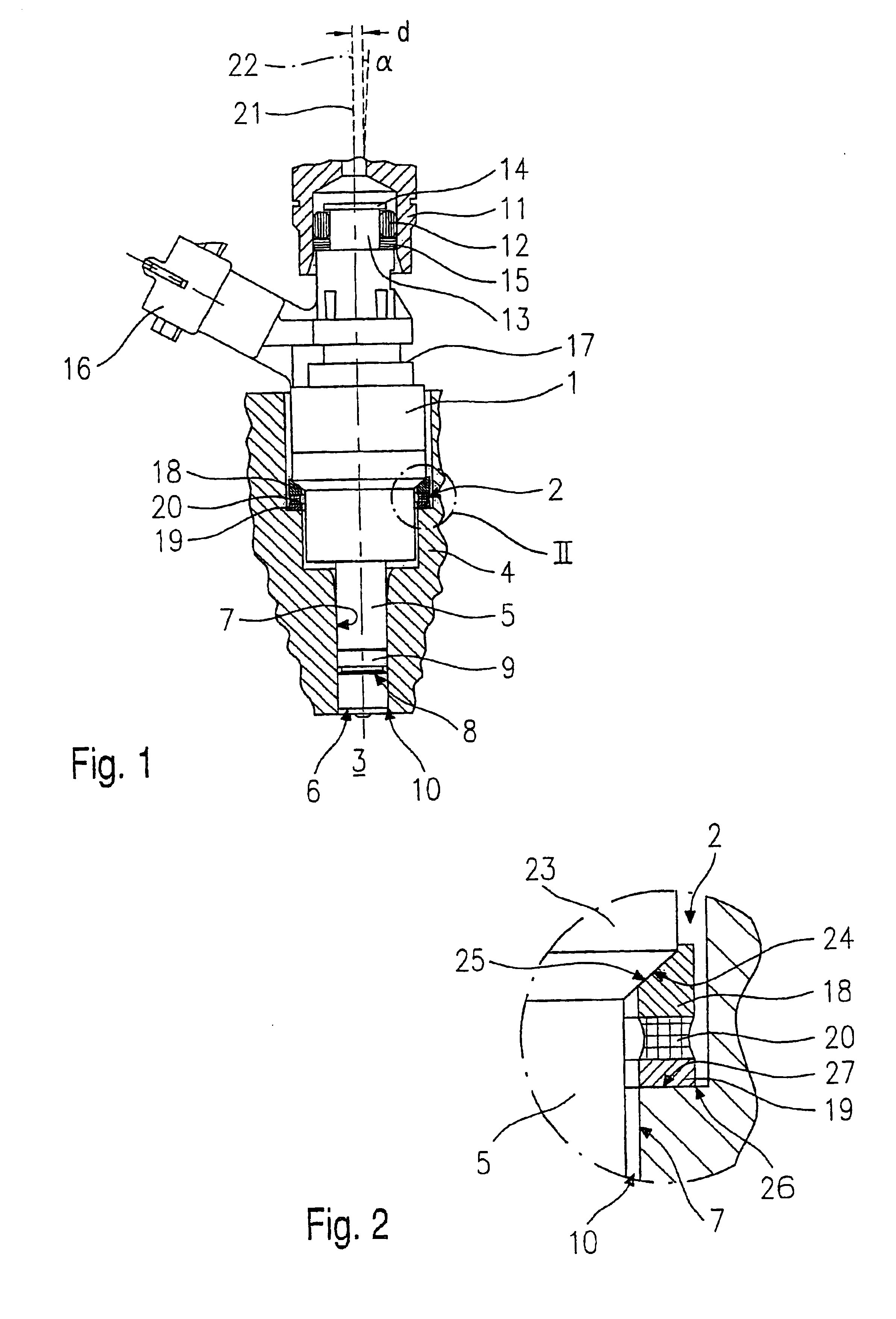
[0020]FIG. 1, in a cross-sect...


PUM


Abstract

A compensating element for a fuel injector, insertable into a receiving bore of a cylinder head of an internal combustion engine, for the direct injection of fuel into the combustion chamber of the internal combustion engine, is provided with a rigid first ring configured to be circumferentially placed against the fuel injector. A rigid second ring is configured to be inserted into the receiving bore. An elastic intermediate ring, positioned between these rigid rings, is permanently joined to the rigid first ring and the rigid second ring.

Description

FIELD OF THE INVENTION[0001]The present invention relates to a compensating element for a fuel injector.BACKGROUND INFORMATION[0002]German Published Patent Application No. 197 35 665 describes a fuel injection system which has a compensating element made of a supporting body having a dome-shaped supporting surface. This compensating element supports a fuel injector in a receiving bore of a cylinder head. Since the fuel injector rests on the spherically shaped calotte surface by way of a supporting surface, the fuel injector can be mounted at an angle that deviates from the axis of the receiving bore by up to a certain amount, and can be pressed firmly into the receiving bore using appropriate means, e.g., a clamping shoe. This allows a simple adaptation to be made to the fuel supply lines. Tolerances arising in the manufacture and in the mounting of the fuel injectors can be compensated for.[0003]It is disadvantageous, however, that the supporting body requires expensive manufacturi...

Claims


Application Information

Patent Timeline
IPC IPC(8): F02M61/00F02M61/14F02F1/24
CPCF02M61/14F02M2200/858
Inventor NORGAUER, RAINER
Owner ROBERT BOSCH GMBH
Why Eureka
Try Eureka