Apparatus for precisely manipulating elongate objects adjacent to and such as energized overhead high voltage transmission lines

a technology of elongate objects and overhead high voltage transmission lines, which is applied in the direction of load-engaging elements, lifting devices, constructions, etc., can solve the problems of requiring the de-energising of a portion of electrical transmission lines, and achieve the effect of changing the angular disposition and orientation

Inactive Publication Date: 2005-01-04
QUANTA ASSOC
View PDF15 Cites 35 Cited by
  • Summary
  • Abstract
  • Description
  • Claims
  • Application Information

AI Technical Summary

Benefits of technology

The present invention may be characterized as an arm, hingedly connectable to the distal end of a hydraulically actuated crane boom and arcuately adjustable by means of an actuator such as a hydraulic ram in a direction generally parallel to the boom so as to effectively change the angular disposition and orientation between the crane boom and the hinged arm. By that adjustment, the arm may be positioned generally horizontally regardless of the boom angle.
The present invention is, thus, in one aspect a device for the precise and remote manipulation of elongate objects adjacent to energized overhead high voltage transmission lines. The device includes in one preferred embodiment, a first and a second arm, where the first arm is rigidly mounted or otherwise fixedly positioned at the distal end of a crane boom and the second arm is hingedly connected to the first arm in proximity to the point of connection between the first arm and the crane boom. Second arm is arcuately adjustable, relative to both the first arm and the crane boom by means of a selectively, actuable actuator such as a hydraulic cylinder mounted so as to be positioned between the first and second arm. The second arm is arcuately adjustable in a direction generally parallel to the boom so as to effectively change the angular disposition between the crane boom and the second arm. By adjusting the angle between first and second arms, the second arm may be positioned in a generally horizontal attitude regardless of the angle of the crane boom and the connected first arm.

Problems solved by technology

However, where a tower supports vertically separated energized lines, wind gusts and rotor downwash make this practice difficult and may require the de-energising of a portion of the electrical transmission line.

Method used


Image

  • Apparatus for precisely manipulating elongate objects adjacent to and such as energized overhead high voltage transmission lines
  • Apparatus for precisely manipulating elongate objects adjacent to and such as energized overhead high voltage transmission lines
  • Apparatus for precisely manipulating elongate objects adjacent to and such as energized overhead high voltage transmission lines

Examples


Embodiment Construction

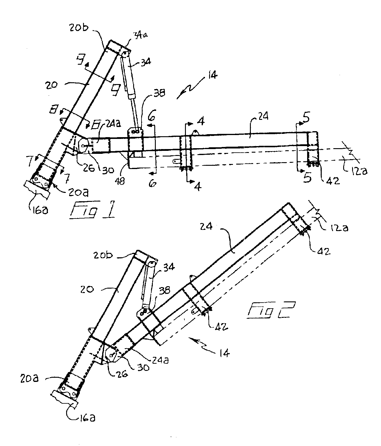
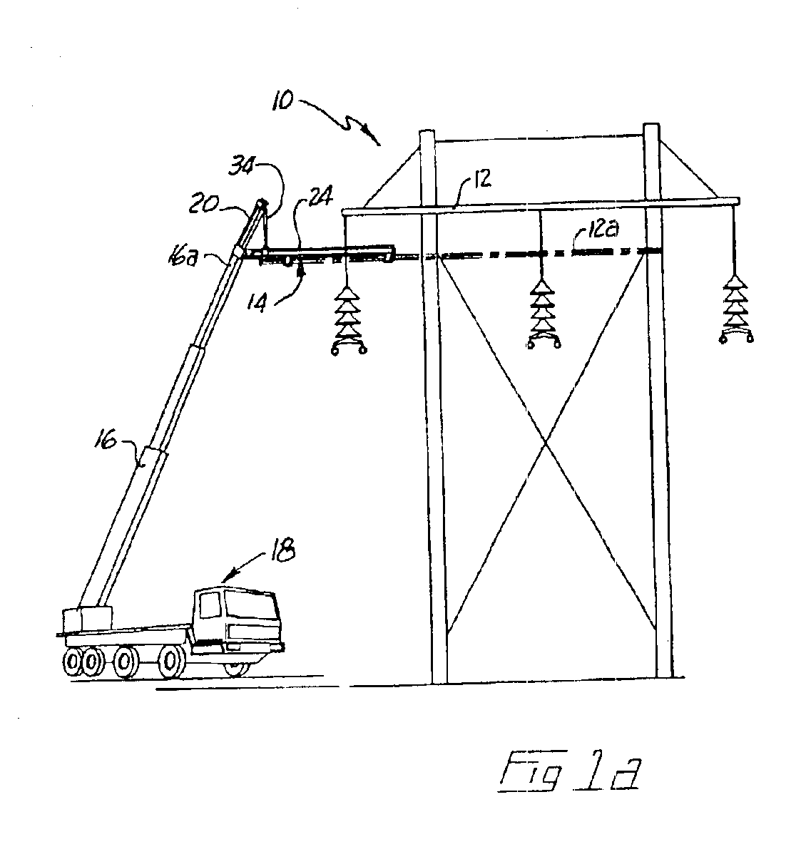
With reference to the drawing figures, wherein similar characters of reference denote corresponding parts in each view, FIG. 1a schematically illustrates a high voltage electrical transmission tower 10 having mounted thereon several cross arms 12. A replacement cross arm 12a (shown in dotted outline) is supported and positioned by a manipulating apparatus 14 according to the present invention, which is mounted to the distal end 16a of a telescopic boom 16 of mobile crane 18.

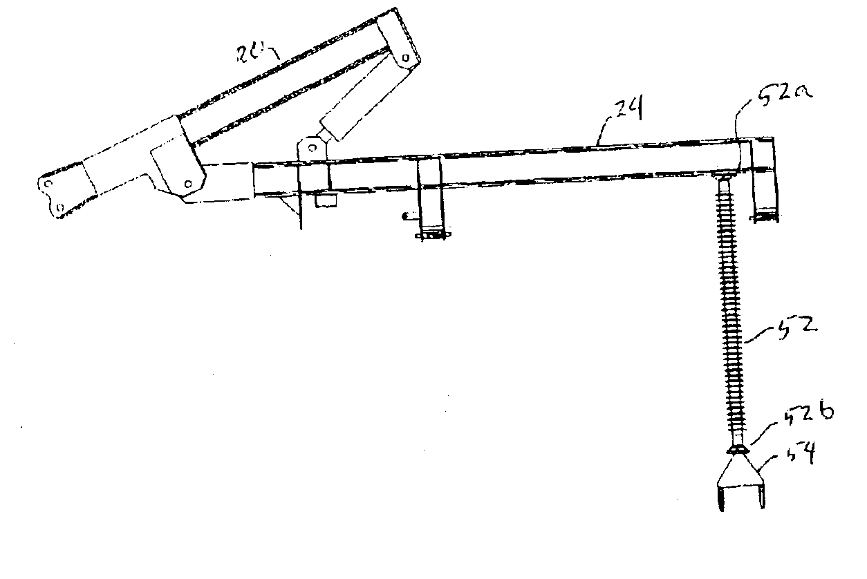
As better seen in FIGS. 1-3, manipulating apparatus 14 has first arm 20 fixedly mounted or secured, for example by bolting or welding, at end 20a, to distal end 16a of crane boom 16. A second arm 24 is hingedly or pivotally mounted or connected to first arm 20. Brackets 26 are welded to first arm 20 in proximity to end 20a. Corresponding brackets 30 are welded at end 24a of second arm 24. Brackets 30 are pivotally mounted to brackets 26. Selectively actuable hydraulic cylinder 34 is mounted so as to extend betwee...


PUM


Abstract

A remotely-controlled manipulator for mounting to the end of a telescopic boom, includes at least one releasable support mounted to a cross member for releasably holding or clamping an elongate object.

Description

BACKGROUND OF INVENTIONThis invention relates to a device which is attached to the boom of a crane, for the precise and remote manipulation of an object such as a cross-arm or insulator, adjacent to energized overhead high voltage transmission lines, or the lines themselves.The replacement and installation of cross arm members or insulators on overhead transmission towers is generally accomplished, whenever possible, while the electrical transmission lines are energized. It is common to find several rows of transmission towers supporting two or more vertically separate electrical transmission lines located in relatively close proximity. This confined overhead working area emphasizes the need for the precise elevating and manipulation of objects so as to avoid accidental arcing between the energized lines and the object with obvious dire consequences to workmen and machinery. A convenient practise is to employ a helicopter to elevate such objects to workmen on the tower. However, whe...

Claims


Application Information

Patent Timeline
Patent Type & Authority Patents(United States)
IPC IPC(8): B66C23/70B66C23/00H02G1/04B66C1/62
CPCH02G1/04B66C23/702
Inventor DEVINE, CLIFFORD WILLIAMO'CONNELL, DANIEL NEIL
Owner QUANTA ASSOC
Why Eureka
Try Eureka